
System Communication Architecture for Search-Drone Return : 911 FALCON Project
Hello, this is QUAD Drone Laboratory.
I’m Geunchan Lee, Senior Researcher at QUAD Drone Lab.
In Week 1, I summarized the background behind launching the 911 FALCON project and outlined the operational concept we designed to address field limitations—namely short flight time and the lack of immediate response capability.
In Week 2, I will introduce the system architecture of 911 FALCON. Focusing on the role split across drone–rover–station and the data/communication flow, I’ll organize the overall operational structure.
Starting Point: “Uninterrupted Search” Enabled by Inter-System Communication & Integration
Even if the drone, rover, and station are each built to a high level of completeness, “uninterrupted search” does not happen automatically. To prevent the search from breaking, position, status, and commands, must be delivered accurately at the right moments between systems, and that data flow must form a single, continuous operational loop.
Ultimately, uninterrupted search is not the performance of a single device, but an operational capability created by a connected architecture designed around communication and data flow.

Core Setup: A Coordinate Update Architecture with a Laptop (QGC) as the Hub
For this architecture to operate reliably, the moving station’s coordinates must continuously reflect the drone’s return destination, and the process must be visible on the control interface. In 911 FALCON, we run QGroundControl (QGC) on a laptop and use it as the operational hub connecting all systems.
In short, the core architectural flow is:
1. Station Position Generation
- As the rover (carrying the station) moves, it continuously generates the station’s latest GPS coordinates.
- These coordinates become the reference for the drone’s return destination—its landing point (operational base).
2. Return Destination Update (QGC)
- The rover periodically transmits the latest coordinates to the laptop (QGC) via Wi-Fi–based UDP.
- The laptop receives these coordinates and continuously updates the Rally Point in QGC, keeping the drone’s RTL destination aligned with the latest station position.
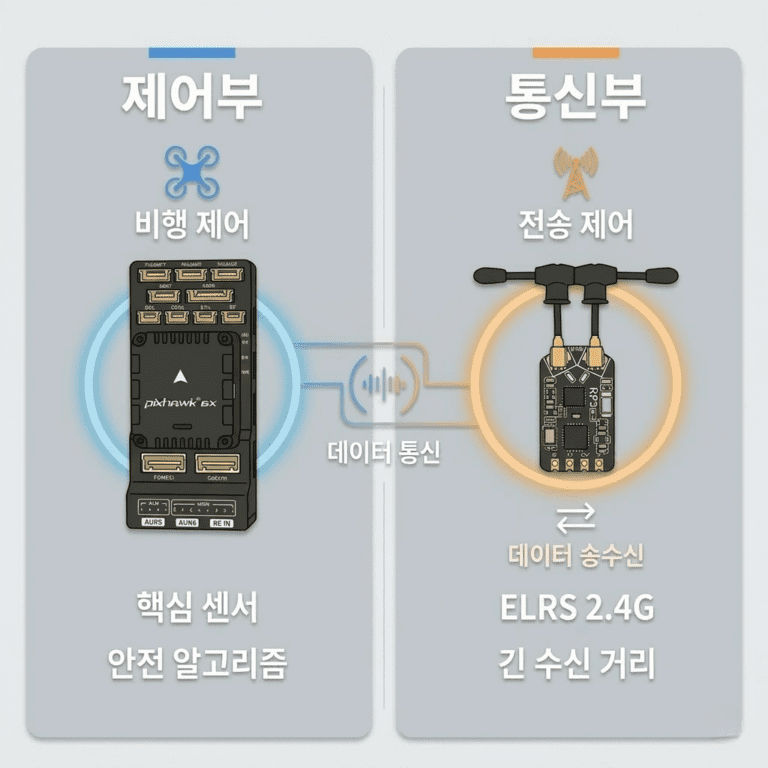
3. Safe Return Execution (PX4 / Drone)
- The drone (PX4) remains connected to the laptop (QGC) via telemetry (MAVLink), maintaining stable monitoring and safety-critical data such as flight status, battery, and modes.
- When the battery reaches a threshold, PX4 switches to RTL and returns to the updated Rally destination (= latest station coordinates).
In other words, the purpose of this structure is not simply to “send coordinates,” but to continuously update the return destination so that continuous operations don’t break.

Precision-Landing Validation via Downward Camera Streaming (Wi-Fi)
Precision landing is largely determined by how stably the marker can be detected in the final moments. Therefore, during development, it is essential not only to judge whether “landing succeeded/failed,” but to tune the system while monitoring both the downward video feed and the detection status.
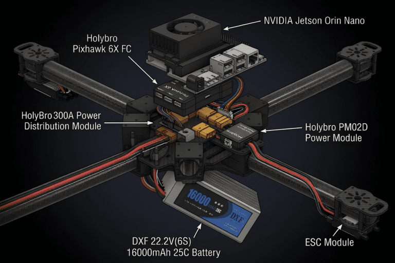
In 911 FALCON, we stream the downward camera footage from the Jetson Orin Nano onboard the drone to the laptop via Wi-Fi. This separates the channels: telemetry remains stable for control and safety, while high-bandwidth data like video is offloaded to Wi-Fi to improve development efficiency.
This setup enables rapid validation of:
- Streaming stability: frame drops, latency, disconnections
- Landing-phase visibility: whether marker/detection status can be confirmed during approach–alignment–descent
- Tuning verification: whether before/after detection results can be compared immediately after parameter changes

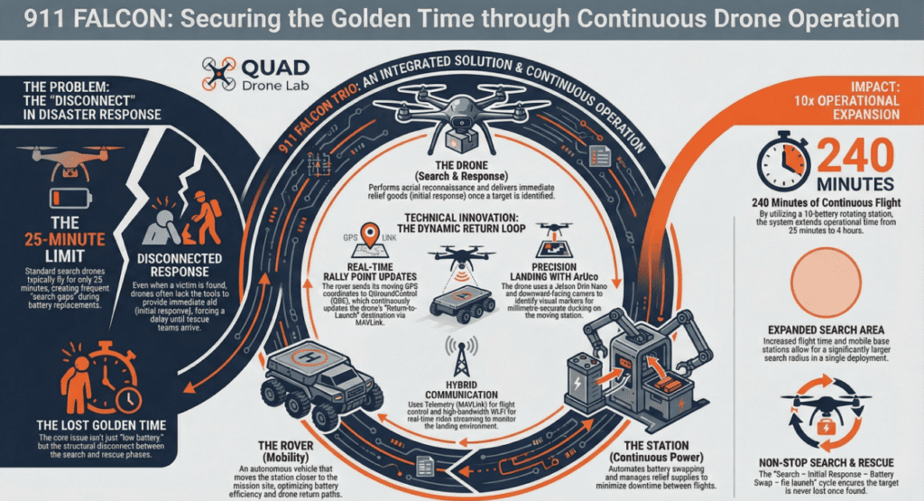
Integrated Scenario: “Search & Delivery → Move → RTL → Precision Landing → Battery Swap”
The full system flow is:
- Drone conducts a search mission and delivers emergency supplies
- Rover moves the operating point (station position changes)
- Rover transmits the latest station GPS to the laptop (UDP)
- Laptop (QGC) updates the drone’s Rally Point to the latest coordinates (MAVLink)
- Battery reaches threshold → PX4 switches to RTL
- Drone returns to the RTL destination (Rally), then performs ArUco-based precision landing
- Station swaps the battery → drone redeploys

Key Takeaway: A Communication Architecture That Enables GPS-Based “Return Destination Updates”
The key point of this post is the architecture that links:
return destination updates reflecting a moving station’s coordinates → stable monitoring via telemetry → precision-landing verification via Wi-Fi video streaming.
Based on this architecture, we will continue implementing and validating the system step by step so that the “search–initial response–redeployment” loop remains uninterrupted in real operations.
In this post, I organized the communication architecture, including the GPS-based return destination update structure.
In the next post, before diving fully into the drone system, I’ll share how we selected the materials (frame/electronics/sensors, etc.) and the criteria behind those choices. After that, I’ll cover the drone build process in stages—CAD design, dimensional verification, fabrication, and assembly. Thank you.

Author: Guenchan lee, Senior Researcher of QUAD Drone Lab.
Date: February 14, 2026
![PX4 MAVSDK – C++ Programming [Episode 11] Complete Comparison of MAVSDK vs MAVROS vs uXRCE-DDS](https://quad-drone-lab.co.kr/wp-content/uploads/2026/03/0322_인포그래피-768x512.png)
![[PX4 Tuning Series 6] Trajectory Generator and Setpoint Tuning: The Art of Flight Feel and Smooth S-Curves](https://quad-drone-lab.co.kr/wp-content/uploads/2026/03/Drone-Trajectory-Comparison-768x429.png)
![PX4 MAVSDK – C++ Programming [9편] 정밀한 드론 제어: 오프보드(Offboard) 모드](https://quad-drone-lab.co.kr/wp-content/uploads/2026/03/0319_인포그래픽-768x429.jpg)
![[PX4 Tuning Series 7] Land Detector Configuration: The Essential Guide for a Perfect Flight Conclusion](https://quad-drone-lab.co.kr/wp-content/uploads/2026/03/Drone-Ground-Contact-Landing-Logic-768x429.png)