

[Hybrid Navigation System Series Part 1: Overview] Flying Hundreds of Kilometers Without GPS? Learning a Hybrid Navigation System from WWII Pilots
Hello, university students and drone researchers who are diving into the world of autonomous flight and navigation systems!
The drones we use every day can locate themselves as quickly and accurately as our smartphones. This is all thanks to the Global Navigation Satellite System (GNSS, commonly referred to as GPS). However, in modern, complex battlefields or dense urban environments, GPS signals are frequently lost due to multipath effects, intentional jamming, and spoofing attacks.
If GPS is completely denied, how can a kamikaze (suicide) drone accurately strike a target hundreds of kilometers away?
In Part 1 of our <Building a ‘Non-GPS Hybrid Unmanned Navigation System’ for Kamikaze Drones> series, we will borrow the wisdom of World War II fighter pilots who navigated the vast Pacific Ocean to find aircraft carriers. We will kindly and thoroughly explore the overview of a ‘3-Stage Hybrid Navigation System’, reinterpreting these historical techniques using modern robotics technologies like ROS 2 and the PX4 Autopilot.
1. Historical Insight: How Did WWII Pilots Find Their Way?
Navigating the endless Pacific Ocean without GPS and successfully returning to a constantly moving aircraft carrier was nothing short of a miracle. Pilots back then survived by combining two core logical methods:
- Dead Reckoning and Overcoming Wind Drift Using their departure point as a reference, pilots mathematically calculated their current position using only a map, a compass (heading), an airspeed indicator, and a clock. Their most terrifying enemy during this phase was ‘wind drift’. Pilots intuitively calculated the difference between their airspeed and ground speed, slightly turning the nose of the plane into the wind—a technique known as ‘crabbing’—to prevent the aircraft from drifting off course.
- Position Reset via Radio Guidance (The YE-ZB System) However, after flying hundreds of kilometers, the mathematical errors in dead reckoning inevitably grew to several kilometers. To solve this, the U.S. Navy introduced a radio beacon system called ‘YE-ZB’. The aircraft carrier divided the 360-degree airspace into 12 sectors of 30 degrees, secretly transmitting a different Morse code on a UHF band for each sector. When a pilot heard a specific Morse code, they could confidently say, “Ah, I am currently between 240 and 270 degrees relative to the carrier!” and mentally reset their accumulated position error back to ‘0’.
We are going to implant this great legacy of the past into the brain of a modern state-of-the-art drone using the PX4 flight control stack and ROS 2.
2. The 3-Stage Architecture of the Hybrid Unmanned Navigation System
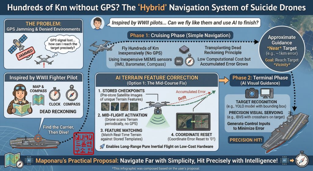
The non-GPS hybrid system we are going to build is tailored for the limited computing resources of a drone. It follows a 3-stage architecture: ‘Go far with simplicity, strike accurately with intelligence’ (Cruise → Mid-course Correction → Terminal Strike).
📍 Stage 1: Cruise Phase – Classic Dead Reckoning & Wind Estimation
This is the long cruise phase where the drone travels hundreds of kilometers towards the target after takeoff. Since GPS is jammed or denied, the drone estimates its position by fusing data from the Inertial Measurement Unit (IMU), magnetometer (compass), airspeed sensor, and barometer.
Because standard low-cost sensors inherently drift (their errors grow infinitely over time), the key here is to integrate an Industrial High-Performance INS (Inertial Navigation System, e.g., Fiber Optic Gyro (FOG) or tactical-grade MEMS) to drastically slow down the rate of error accumulation. Furthermore, PX4’s EKF2 (Extended Kalman Filter) module utilizes the drone’s drag specific forces and airspeed to estimate real-time wind direction and wind speed (Wind Velocity North/East).
- Example: Wind Correction Angle (WCA) Control Logic (C++/ROS 2) If we translate the crosswind correction calculations previously done by human pilots into modern C++ algorithms, it looks like this:
// 1. Gather Sensor and EKF2 Data
float V_a = current_true_airspeed; // Drone's True Airspeed (TAS)
float V_wN = wind_state_north;     // EKF2 estimated North wind velocity
float V_wE = wind_state_east;      // EKF2 estimated East wind velocity

// 2. Calculate Absolute Wind Speed (V_w) and Direction (wind_dir)
float V_w = sqrt(V_wN*V_wN + V_wE*V_wE);
float wind_dir = atan2(V_wE, V_wN);

// 3. Calculate Relative Angle (theta) between Target Course and Wind Direction
float target_course = atan2(target_Y - current_Y, target_X - current_X);
float theta = wind_dir - target_course;

// 4. Calculate Wind Correction Angle (WCA) to overcome Crosswind
// WCA = arcsin((WindSpeed * sin(theta)) / TrueAirspeed)
float crosswind = V_w * sin(theta);
float WCA = asin(crosswind / V_a);

// 5. Publish the Final Required Heading to the PX4 Offboard Topic
float required_heading = target_course - WCA;
trajectory_setpoint_msg.yaw = required_heading;
Through this process, even in strong crosswinds, the drone will silently maintain a straight ground track toward the target area.
📍 Stage 2: Mid-course Correction Phase – Terrain Feature-Based Position Reset (Pseudo-YE-ZB)
No matter how outstanding your high-performance INS is, flying for hundreds of kilometers will inevitably result in a dead reckoning drift of 1 to 2 kilometers. Just as the historical YE-ZB radio system reset the pilot’s errors, we will substitute this with Terrain Referenced Navigation (TRN).
There is no need to store massive satellite maps of the entire route on the drone. Instead, we only store ‘Template Images’ of highly distinctive mid-flight checkpoints (e.g., unique coastlines, isolated islands, distinct bridge intersections). When the drone estimates it has reached the vicinity of a checkpoint, it activates its downward-facing camera. Using OpenCV’s cv2.matchTemplate() function or YOLO-based landmark object detection, it matches the real-time terrain with the stored template.
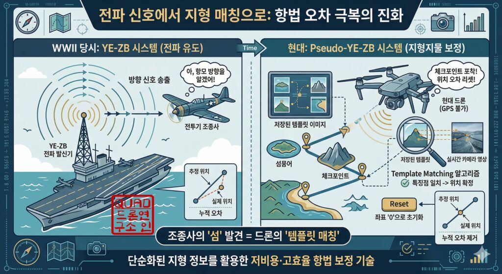
The moment the feature points align, the drone realizes, “Ah, I am exactly above this specific island (absolute coordinates)!” At this instant, the system forcefully resets (Loop Closure) the distorted local coordinates of the EKF2 to these absolute coordinates, wiping out the kilometers of accumulated drift in a single stroke.
📍 Stage 3: Terminal Phase – Precision Visual Servoing (IBVS)
When the drone finally reaches the radius of the target, it transitions to the ‘Terminal Phase’ for the final precision strike (or landing). This mimics the historical pilot visually spotting the enemy aircraft carrier from a distance and initiating a dive-bombing run.
At this point, flying to a specific “coordinate” on a map is meaningless (the target might be moving, or the coordinates might be slightly off). Instead, the drone uses its onboard front-downward camera and a deep learning object detection algorithm like YOLOv8 to capture the silhouette of the target (e.g., an enemy tank, a bunker, or a specific marker).
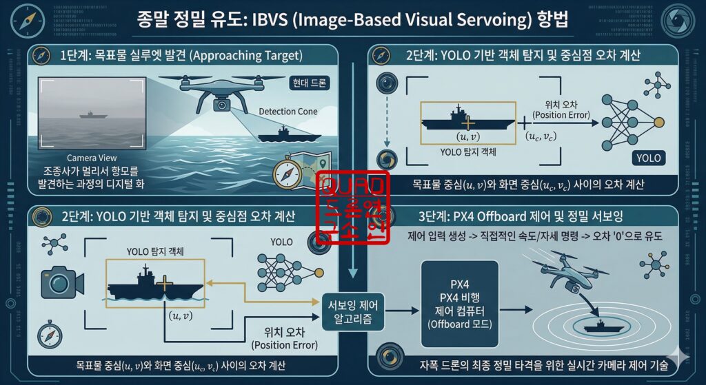
Once the camera locks onto the target, the system calculates the Position Error between the target’s center pixel (u,v) and the actual camera frame’s exact center pixel (uc,vc). The technique of generating control inputs to make this error ‘0’ is known as Image-Based Visual Servoing (IBVS).
Our ROS 2 system takes this pixel error, generates a direct Velocity Setpoint, and commands the drone continuously via PX4’s Offboard Mode.
- Example: PX4 Offboard Velocity Control (ROS 2 Python)
# Calculate target center error (e.g., converting pixel error to velocity command)
error_x = target_u - image_center_u
error_y = target_v - image_center_v

# Generate velocity commands via Proportional (P) Control
vel_x = Kp * error_y  # Y-axis error in the image translates to drone's forward (X) velocity
vel_y = Kp * error_x  # X-axis error in the image translates to drone's lateral (Y) velocity

# Publish the TrajectorySetpoint message
msg = TrajectorySetpoint()
msg.position = [float('nan'), float('nan'), float('nan')] # Ignore position control
msg.velocity = [vel_x, vel_y, descent_velocity]           # Activate velocity control
msg.yaw = target_yaw
self.trajectory_setpoint_publisher.publish(msg)
By controlling the vehicle’s speed using visual feedback rather than fixed coordinates, the drone can continuously track and precisely strike the target, even if the target is actively moving evasively!
🚀 Wrapping Up
So far, we have looked at the overall blueprint of the ‘3-Stage Non-GPS Hybrid Navigation System’, a system that resurrects the dead reckoning and radio guidance logic of WWII pilots using modern robotics technology.
In this system, the strengths of each algorithm compensate for the others’ weaknesses. The ‘drift accumulation’ of Dead Reckoning is solved by the ‘absolute position reset’ of Terrain Matching. And in the final unknown strike zone where terrain data might be absent, ‘Visual Servoing’ takes over to complete the mission flawlessly.
In our next post, Part 2, we will dive deep into the fundamental principles of the brain behind autonomous flight—PX4’s EKF2—and detail how to set up a Gazebo SITL (Software In The Loop) simulation environment. This will allow you to develop and test this incredible system safely without risking damage to expensive hardware.
Please look forward to the upcoming integration of ROS 2 coding and computer vision (OpenCV/YOLO) in the rest of the series!
YouTube

Author: maponarooo, CEO of QUAD Drone Lab
Date: April 11, 2026
![PX4 MAVSDK – C++ Programming [Episode 11] Complete Comparison of MAVSDK vs MAVROS vs uXRCE-DDS](https://quad-drone-lab.co.kr/wp-content/uploads/2026/03/0322_인포그래피-768x512.png)
![PX4 MAVSDK – C++ Programming [12편] MAVSDK C++를 활용한 최신 자율 비행 연구 사례](https://quad-drone-lab.co.kr/wp-content/uploads/2026/03/0322_인프그래피2-768x429.jpg)