
Frame Design and Main Component Layout : 911 FALCON Project
Hello, this is QUAD Drone Laboratory.
I’m Geunchan Lee, Senior Researcher at QUAD Drone Lab.
In the previous article, we reviewed the design process and component selection for the Control & Communication System of the 911 FALCON drone. We covered the selection criteria for key components including the Flight Controller and Companion Computer responsible for flight control, as well as the GPS, control link, video transmission system, and telemetry communication devices that connect the aircraft to external systems. Finally, we also examined the overall control and communication architecture to show how these devices are interconnected within the system.
In this article, we move on to the next stage and discuss the frame design and main component layout, which define how the selected systems are physically integrated into the aircraft structure.
We will first review the reverse-engineering process of the HTX415 frame, based on its datasheet and actual measurements, and examine its key structural characteristics. Then, we will explain the criteria used to arrange major components such as the Power Module, PDB, FC, Jetson Nano, Battery, and ESCs within the frame. Finally, we will summarize the overall structural layout centered on the frame, showing how each component is positioned and integrated into the aircraft system.

1. Frame Design
1-1) Reference Frame Selection and Design Approach
Product:
HTX415 4-Axis 15-Inch Frame

The airframe of the 911 FALCON was designed based on the HTX415 4-Axis 15-Inch Frame. At this stage, rather than revisiting the reasons for selecting the frame or explaining its specifications again, we focused on organizing the structure of the already selected frame so that it could be applied to actual fabrication and the layout design of major components.
To achieve this, the frame geometry was first organized as a reference model in CAD, providing a design foundation for reviewing whether major components could be mounted, how they should be oriented, and whether interference would occur between parts. Therefore, this frame design stage was not simply about external modeling, but rather a preliminary design process for actual assembly and internal structural integration.
1-2) Reverse Engineering Based on Datasheet and Actual Measurements
Although the HTX415 frame is a commercial product, it was difficult to obtain an official CAD file in a form that could be directly used for the layout of major components and internal structural review. Therefore, in this project, reverse engineering was carried out by referring to the basic dimensional information provided in the product datasheet and supplementing the missing dimensions through direct measurement of the main parts of the actual frame.
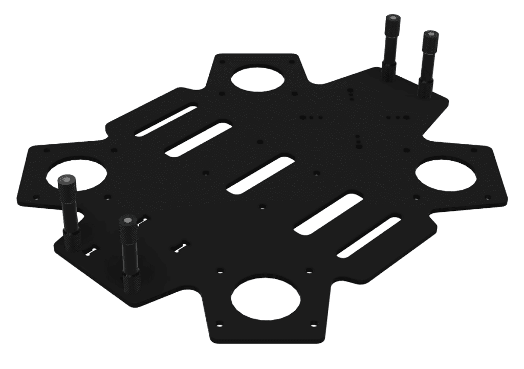
In the reverse-engineering process, the frame structure was organized with a focus on the upper and lower plate geometry, stack spacing, arm joint structure, mounting hole locations, and available internal space. The purpose of this process was not to completely reproduce the frame at the level of a precision manufacturing drawing, but rather to secure a reference model that could be used to evaluate the mountability and placement direction of the main components.
In addition, the reference model, organized using both the datasheet and actual measurements, was structured so that it could be used in later stages for wiring path design, assembly feasibility verification, and interference checks between components. Through this process, a more systematic foundation was established for reviewing the internal structure of the aircraft before actual fabrication.
1-3) Structural Characteristics of the Frame
After organizing the basic geometry of the frame through reverse engineering, we also examined how the actual structure of the HTX415 is configured.
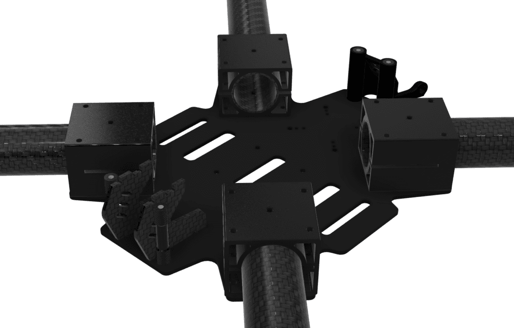
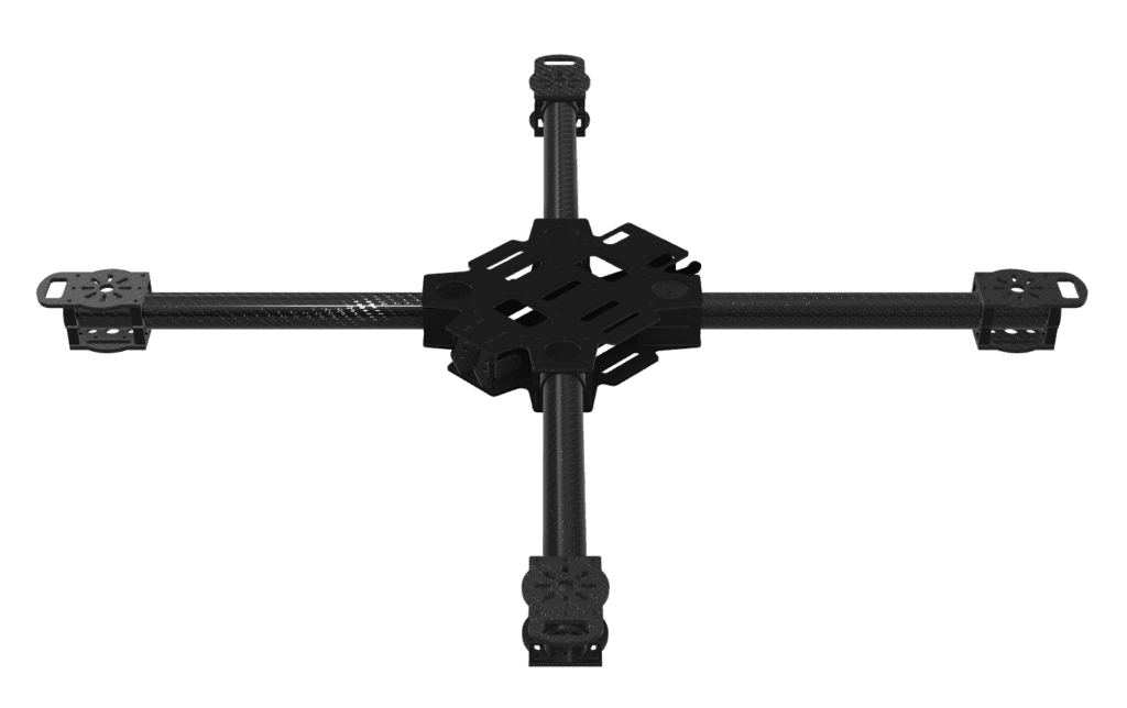
The frame consists of upper and lower carbon plates, with four standoffs positioned at the front and rear between the two plates to form the internal space. This structure secures a certain amount of stack space at the center of the aircraft and provides the basic framework for mounting internal electronic components.
In addition, aluminum inserts for fastening the arms are positioned along each diagonal direction, and these inserts are bolted together between the upper and lower plates. In other words, rather than having the upper and lower plates separated from the arm joints, the structure is designed so that they are integrated into a single fastening system, which contributes to both the overall rigidity of the frame and its assembly structure.
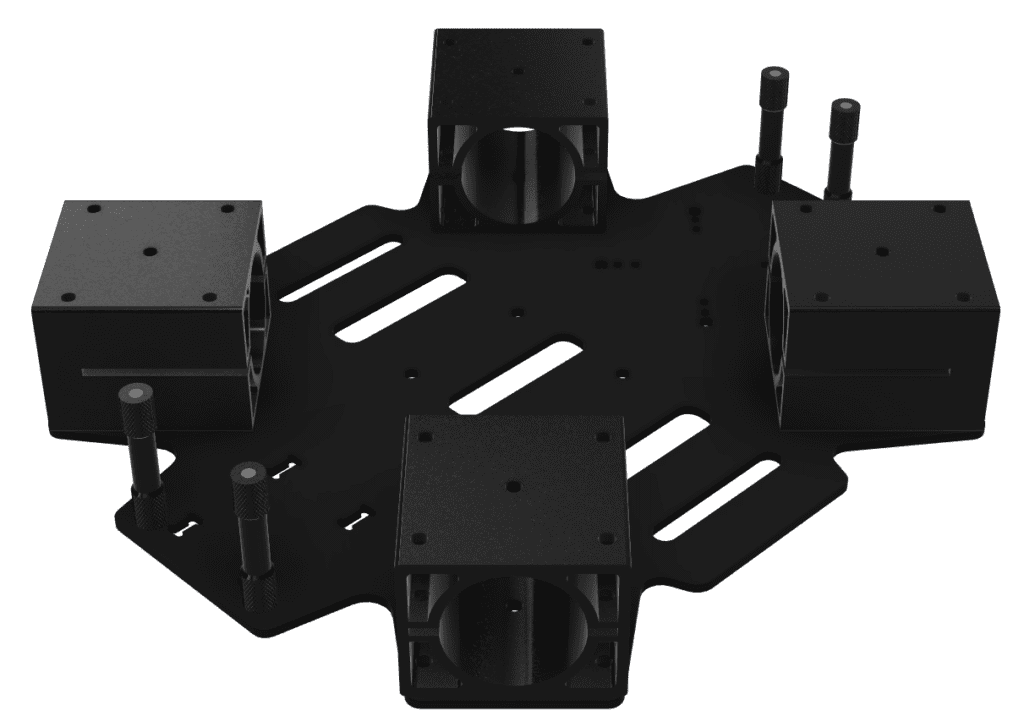
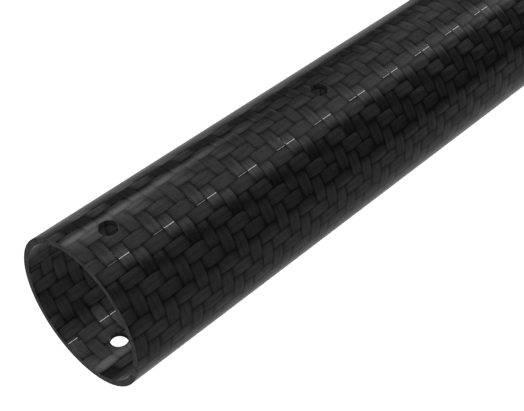
The frame arms are made of carbon pipes, and an insert hole is machined at the center of each pipe. This insert hole is designed to align with the center of the aluminum insert, allowing the arms to be fixed to the main frame structure through bolting. Through this arrangement, the arms are integrated with the central frame structure and form a stable support configuration along each axis.
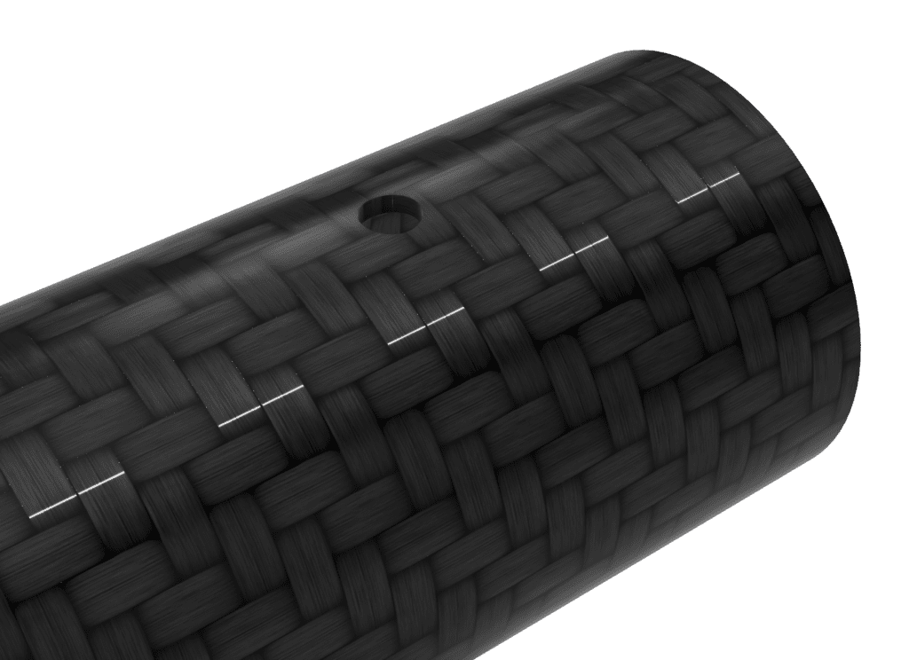
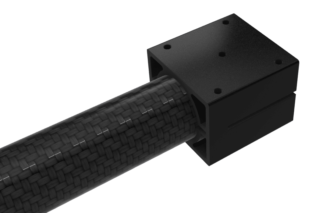
In addition, separate insert holes are machined at the ends of the carbon pipes for fastening the motor inserts and plates. By aligning the motor mounts with these hole positions and securing them through bolting, the motors can be mounted to the frame. As a result, the structure is configured so that the central frame body, arms, and motor mounts are connected in sequence.
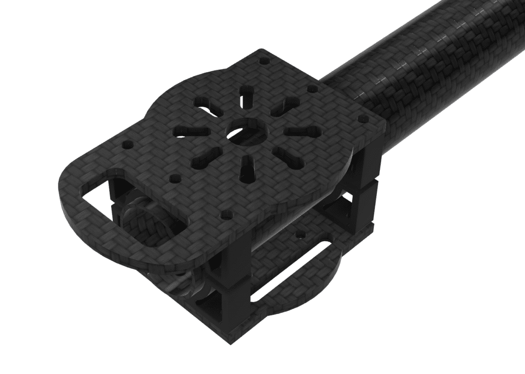
In this way, the HTX415 frame is composed of upper and lower plates, standoffs, aluminum inserts, carbon pipe arms, and motor mount joints, forming an assembly-type frame structure in which each part is connected by bolting. Based on this understanding, the overall frame geometry in this stage was organized to reflect the structural characteristics of the frame.
2. Main Component Layout
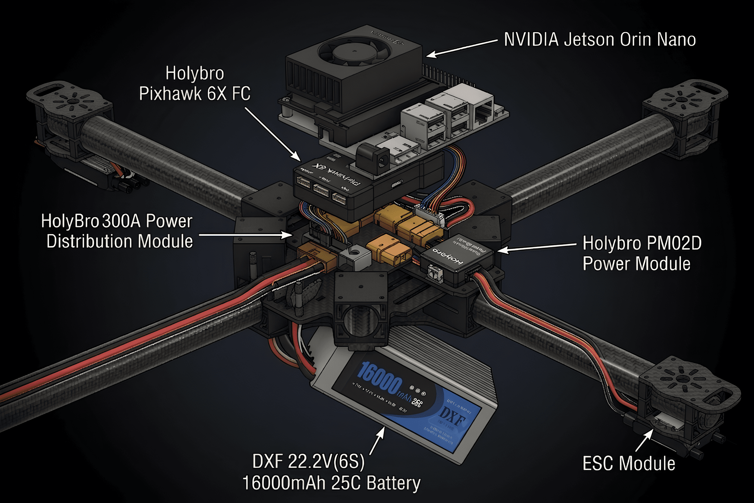
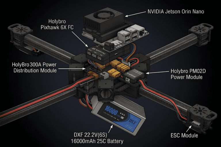
After organizing the overall geometry of the frame, we then reviewed the criteria for arranging the main components within it. In this layout design stage, the target components included the Power Module, PDB, FC, Jetson Nano, Battery, and ESCs, and for each component, we sequentially examined the required conditions, the location within the airframe, and the reasons for selecting that position.
The main component layout was not approached simply by fitting parts into empty spaces, but by considering the function and role of each device, along with factors such as power flow, center of gravity, wiring length, heat dissipation, vibration, and maintainability.
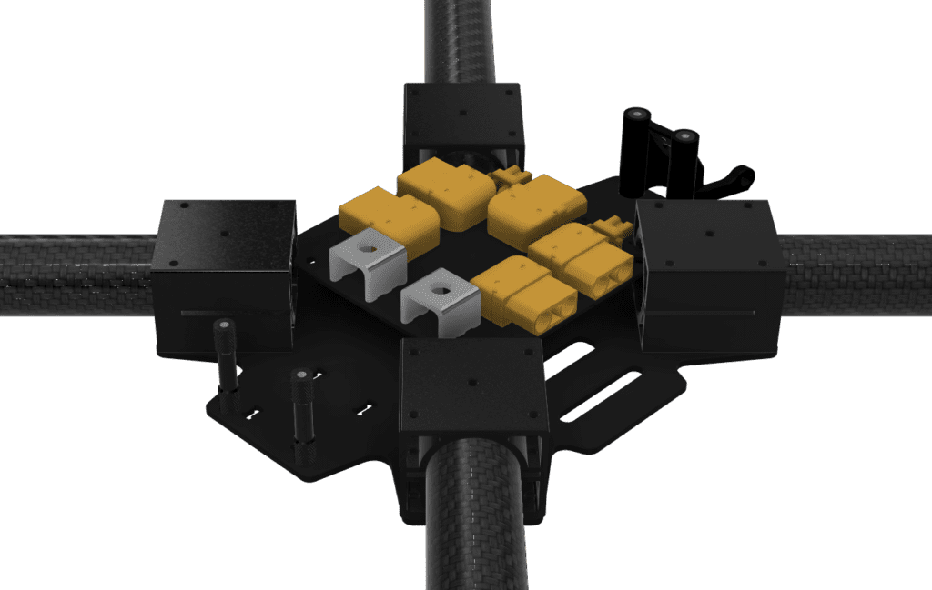
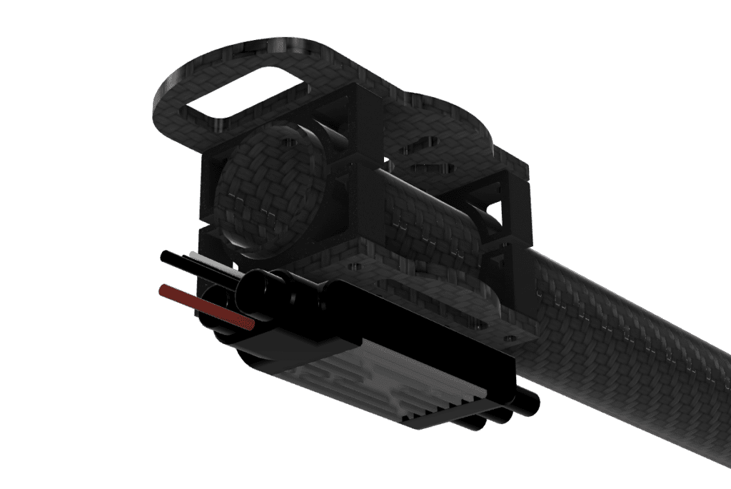
2-1) Power Module
Product :
Holybro PM02D Power Module

Requirements
The Power Module must be able to stably deliver the power supplied from the battery to the FC and the overall power system, while also measuring voltage and current information. Therefore, it is important for the module to be located along the power path between the battery and the PDB, and the wiring length in the high-current section should be kept as short as possible.
Placement
The Power Module was placed along the main power input path at the center of the aircraft.
Reason for Placement
By placing it at the center of the aircraft, the incoming power from the battery can be monitored first in a stable manner, and the subsequent power flow to the PDB and FC can be configured relatively simply. In addition, the connection distance between the battery and the PDB can be reduced, which is beneficial for both power system wiring organization and maintainability.
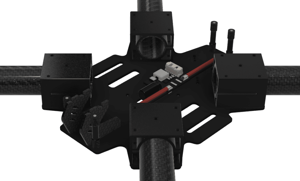
2-2) PDB
product :
HolyBro 300A Power Distribution Module

Requirements
The PDB is responsible for distributing the power supplied from the battery to each ESC and major device. In particular, since this PDB must be connected to the main power lines of the motors through four XT90 pins, it needs to be positioned close to the motor power cables entering from the directions of the carbon pipe arms. In addition, the PDB should be placed near the center of the aircraft so that the overall power wiring does not become excessively long.
Placement
The PDB was placed at the center of the frame, between the upper and lower plates.
Reason for Placement
Placing the PDB at the center of the frame allows it to be positioned close to the Power Module, which simplifies the organization of the main power input path. It also provides easy access to the motor power cables coming from each carbon pipe arm. In addition, because it is located at the center, it was considered an advantageous position for configuring the wiring needed to supply power to other devices through the XT30 connectors.
However, since the frame does not provide suitable mounting holes for directly securing the PDB, a dedicated mounting bracket will need to be separately designed and applied for actual installation.
2-3) FC
Product :
Holybro Pixhawk 6X

Requirements
The FC is the core device responsible for the aircraft’s attitude control, so it must be placed close to the center of gravity and positioned in a way that minimizes the influence of external vibration. In addition, considering its connections to the power system, communication devices, and companion computer, accessibility and wiring organization also need to be taken into account.
Placement
The FC was placed at the center of the upper plate of the drone.

Reason for Placement
The center of the upper plate is close to the main axis of the aircraft, making it a favorable location for IMU-based attitude estimation and control stability. In addition, it allows the connection paths to the power system, communication devices, and Companion Computer to be organized relatively efficiently, and was therefore considered suitable for the overall configuration of the control system.
However, since the upper plate of the frame does not provide suitable mounting holes for directly installing the FC, a dedicated mounting bracket will be separately designed and applied during the actual installation stage.
2-4) Jetson Nano
Product :
NVIDIA Jetson Orin Nano
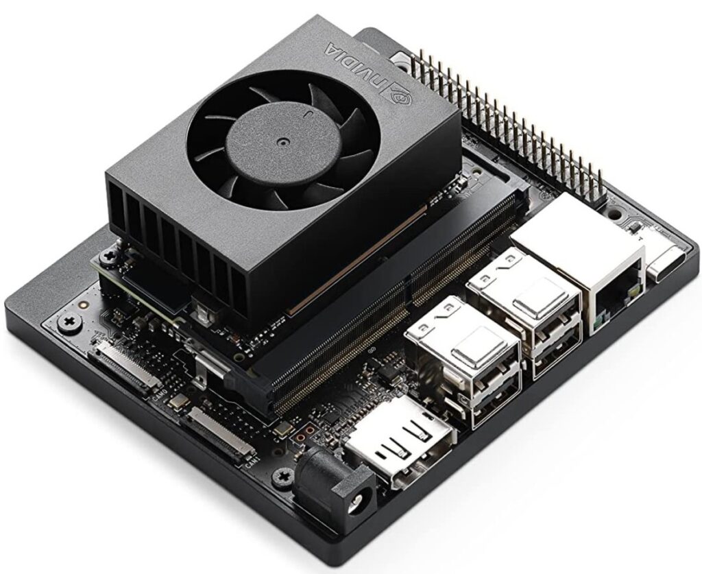
Requirements
Since the Jetson Nano performs vision processing and onboard computation, it must be able to communicate with the FC, while also accommodating interface connections with the camera and other peripheral devices. In addition, given the characteristics of a computing device, sufficient consideration must be given to heat dissipation space and accessibility.
Placement
The Jetson Nano was placed in the upper stack space near the FC.
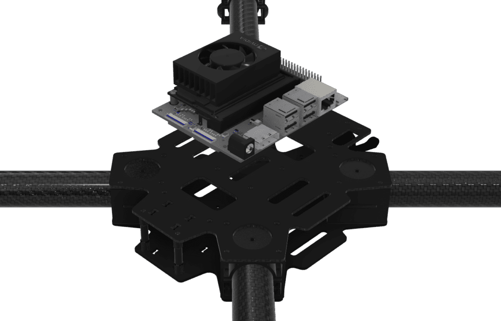
Reason for Placement
Placing it in the upper stack space makes communication with the FC easier and is also advantageous for configuring interfaces with the camera and other expansion devices. In addition, compared with the more confined internal central space, this location offers better space utilization and accessibility, which is beneficial for maintenance. It was also considered an appropriate position because the computing device, which generates heat during operation, can be separated and arranged in an independent stack space.
However, due to the frame structure, there are no suitable mounting holes for directly securing the Jetson Nano, so a dedicated mounting bracket will need to be separately designed and applied for actual installation.
2-5) Battery
Product :
DXF 22.2V(6S) 16000mAh 25C

Requirements
Since the battery is one of the heaviest components in the aircraft, it needs to be placed as close as possible to the center of gravity. In addition, since this project is intended to incorporate an automatic battery replacement mechanism in the future, the design must consider not only a simple fixed-mount structure but also a configuration that allows the battery to be inserted and removed.
Placement
The battery was placed at the center of the underside of the lower plate.
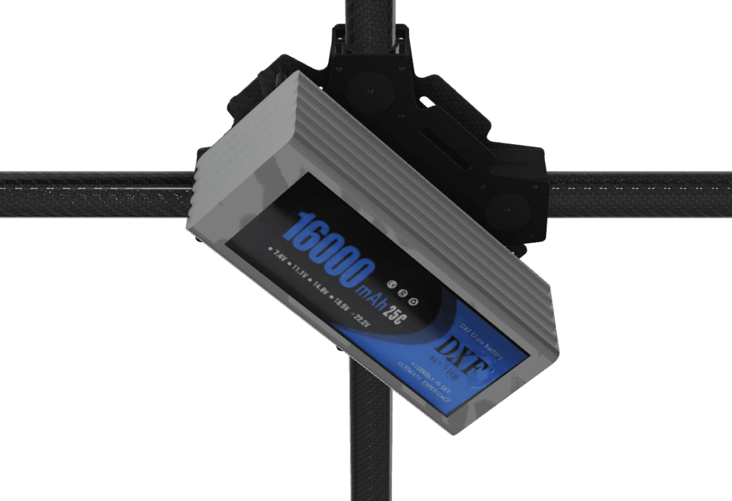
Reason for Placement
Placing the battery at the center of the underside of the lower plate allows it to be positioned close to the main axis of the aircraft, which is advantageous for securing a stable center of gravity. In addition, a battery housing for future automatic replacement is planned to be mounted below this location, and through this housing, a slider-based fastening structure will be applied to enable battery installation and removal.
Therefore, placing the battery at the center of the underside of the lower plate is not only effective for securing the center of gravity of the aircraft, but also represents a layout direction that takes into account future integration with the automatic battery replacement system.
2-6) ESC
Product :
XRotor PRO 60A ESC

Requirements
The ESCs are devices that handle high current while being directly connected to each motor, so they need to be placed close to the motors and arranged in a way that allows effective heat dissipation. In addition, it is also important to position them so that they do not occupy too much of the internal central space.
Placement
The ESCs were placed beneath each motor mount.
Reason for Placement
Placing the ESCs beneath each motor mount helps reduce the wiring length to the motors, allowing the power cable arrangement to be organized more simply. It also prevents heat from being concentrated in the central section of the frame, which is advantageous in terms of thermal distribution. In addition, this layout allows the central space to be prioritized for key components such as the FC, PDB, and Battery.
However, since the frame structure does not provide suitable mounting holes for directly securing the ESCs, a separate dedicated mounting bracket will need to be designed and applied for actual installation.
Main Component Layout Summary
The following summarizes the layout structure of the main components.

The 911 FALCON drone was designed based on the HTX415 frame, with the Power Module, PDB, Pixhawk 6X, Jetson Orin Nano, battery, and ESCs placed in appropriate positions according to the role and requirements of each component.
In this article, we reviewed the frame geometry and the layout direction of the main components based on the airframe of the 911 FALCON drone. The HTX415 frame was reverse-engineered using its datasheet and actual measurements, and based on this reference model, the Power Module, PDB, Pixhawk 6X, NVIDIA Jetson Orin Nano, battery, and ESCs were arranged in positions suited to the role and requirements of each component.
In the next article, based on the main component layout reviewed here, we will focus on the dedicated mount design process for components that require separate mounting structures, such as the PDB, Pixhawk 6X, NVIDIA Jetson Orin Nano, and ESCs. We will examine how each component will be secured, how the mounting structures will be integrated with the frame, and what design criteria and geometries were applied for actual assembly. Thank you.

Author: Guenchan lee, Senior Researcher of QUAD Drone Lab.
Date: March 24, 2026
![PX4 MAVSDK – C++ Programming [Episode 11] Complete Comparison of MAVSDK vs MAVROS vs uXRCE-DDS](https://quad-drone-lab.co.kr/wp-content/uploads/2026/03/0322_인포그래피-768x512.png)
![PX4 MAVSDK – C++ Programming [Episode 7] Moving to a Specific Location (goto_location) and Understanding the Haversine Formula](https://quad-drone-lab.co.kr/wp-content/uploads/2026/03/0317_인포-768x512.png)
![[MAVSDK C++ Part 4] Building Your Own App: Project Setup and Drone Connection](https://quad-drone-lab.co.kr/wp-content/uploads/2026/03/0314_인포그래피-768x512.png)
![PX4 MAVSDK – C++ Programming [12편] MAVSDK C++를 활용한 최신 자율 비행 연구 사례](https://quad-drone-lab.co.kr/wp-content/uploads/2026/03/0322_인프그래피2-768x429.jpg)