
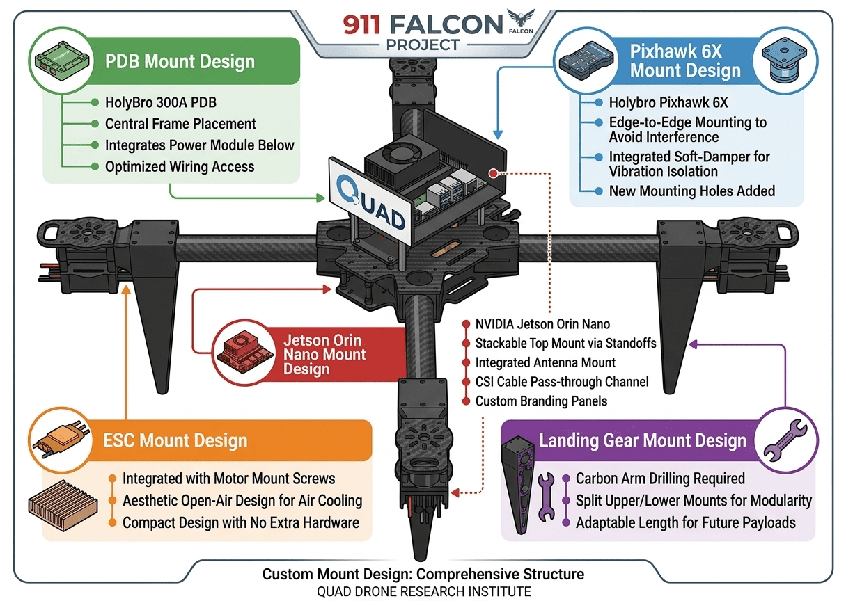
Main Component Mount Design : 911 FALCON Project
Hello, this is QUAD Drone Laboratory.
I’m Geunchan Lee, Senior Researcher at QUAD Drone Lab.
In the previous article, we organized the airframe structure of the 911 FALCON drone and reviewed the placement directions of the main components. Based on the datasheet and direct measurements, we reverse-engineered the HTX415 frame and arranged the Power Module, PDB, Pixhawk 6X, NVIDIA Jetson Orin Nano, battery, and ESC in positions that matched each component’s role and design requirements.
However, during the layout review, we found that some components did not have suitable fastening structures for direct installation on the frame. In particular, the PDB, Pixhawk 6X, NVIDIA Jetson Orin Nano, ESC, and landing gear could not be mounted properly using only the original frame structure, which made it necessary to design dedicated mounts for each of them.
In this article, we will focus on the design criteria used to develop these dedicated mounts for actual integration into the airframe, as well as the structural constraints and interference issues that had to be considered throughout the design process.
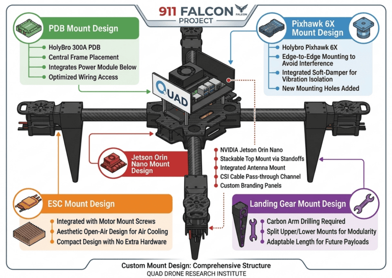
1. Mount Design
1-1) PDB Mount Design
Product :
HolyBro 300A Power Distribution Module

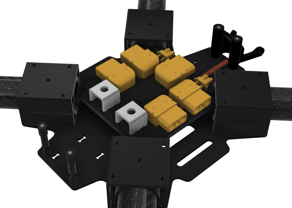
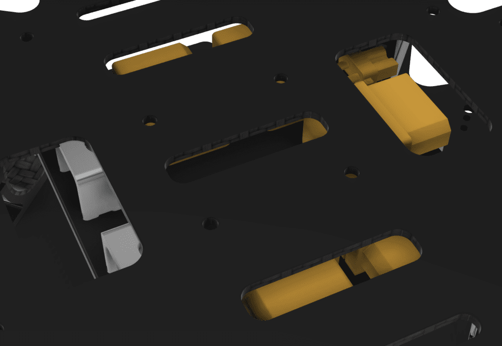
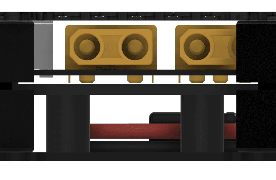
When designing the dedicated PDB mount, the first point we considered was that the PDB had to be placed at the center of the frame, between the top and bottom plates, while the Power Module also needed to be positioned underneath it. Therefore, the structure could not simply be a mount for fixing the PDB alone. Instead, it had to accommodate both components within the central stacked space, and because the main power lines from each motor are connected to the PDB, it was also necessary to reflect both the power distribution path and wiring accessibility in the design.

However, the available space inside the frame was quite limited, and the mount geometry was especially constrained by the aluminum inserts located around the central section, which are used to fasten the arms. In other words, although the PDB had to be positioned at the center of the frame, a simple flat-plate structure could easily interfere with these inserts. In addition, sufficient vertical clearance also had to be secured for the Power Module placed beneath the PDB, which meant that multiple internal space constraints had to be addressed at the same time.
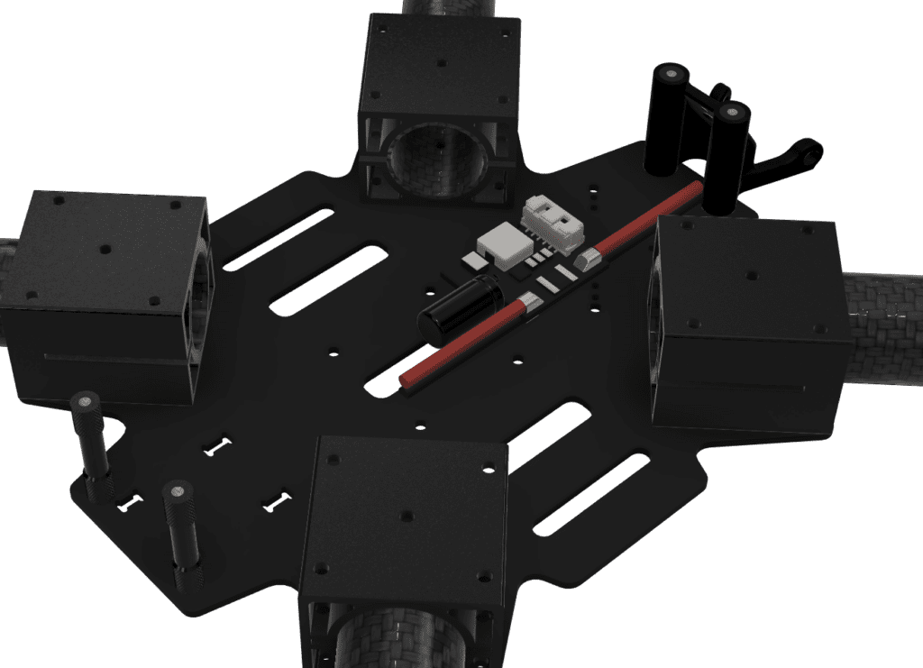
Therefore, the dedicated PDB mount was designed with an outer profile that avoids interference with the aluminum inserts, while also fitting within the available height and width between the top and bottom plates. In addition, the mount height was defined to secure enough lower clearance so that the Power Module could be housed beneath the PDB. As a result, this PDB mount was designed not as a simple board-fixing part, but as a structural component intended to accommodate both the PDB and the Power Module within the limited central stacked space.
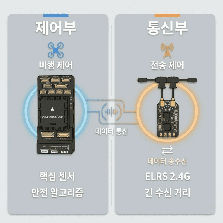
1-2) Pixhawk 6X Mount Design
Product :
Holybro Pixhawk 6X

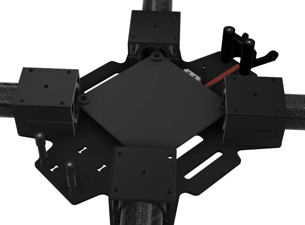
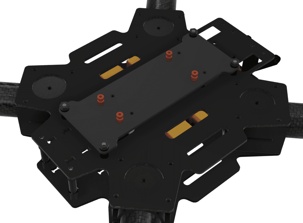
When designing the dedicated Pixhawk 6X mount, the first point we considered was that the flight controller had to be positioned at the center of the top plate, while also ensuring that vibration would not be directly transmitted during installation. In addition, because the Pixhawk 6X is directly involved in attitude estimation and flight stabilization, the design needed to incorporate not only a secure mounting structure but also an effective vibration isolation mechanism.
At first, we considered a mounting method that used the existing holes at the center of the top plate. However, as the PDB mount became taller in order to secure space for the Power Module underneath, interference occurred between the bolt heads used to fasten the PDB mount and those required for the flight controller mount. As a result, it became difficult to secure sufficient installation space using only the original central holes, and this approach also made it difficult to resolve interference with the lower structural components.
Therefore, the Pixhawk 6X mount was revised to use the holes located near the edge of the top plate instead of the original central holes. However, while usable holes were available on the upper side, there were no corresponding holes on the lower side, so additional fastening holes were created by directly drilling at appropriate positions. In addition, soft dampers were inserted at each mounting bolt location to prevent airframe vibration from being directly transmitted to the flight controller. As a result, this Pixhawk 6X mount was designed as a dedicated mounting structure that avoids interference with the lower components while also incorporating a vibration isolation mechanism.
1-3) NVIDIA Jetson Orin Nano Mount Design
Product :
NVIDIA Jetson Orin Nano
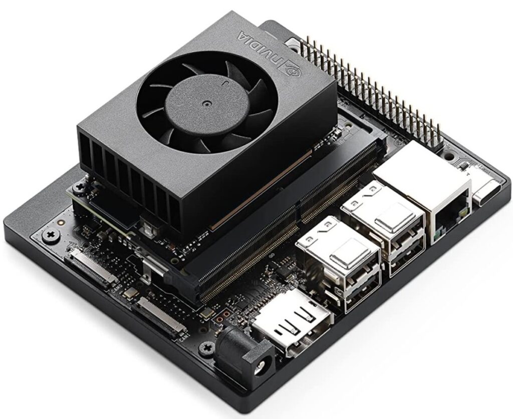
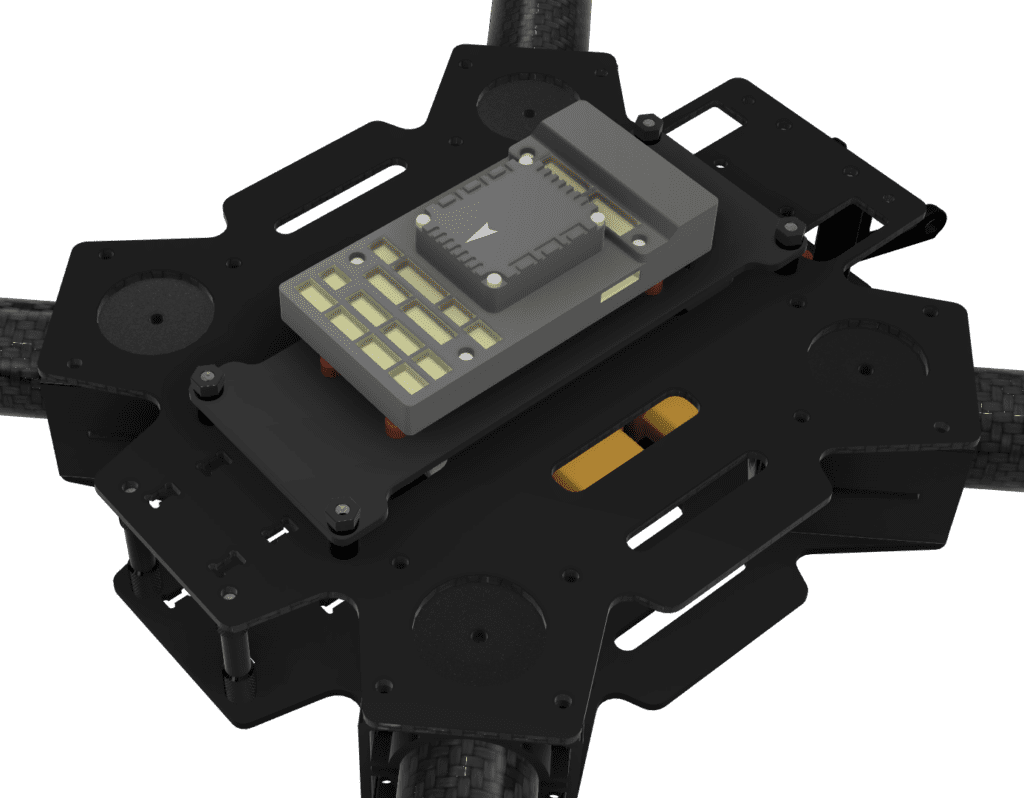
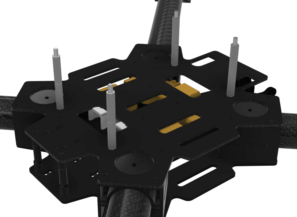
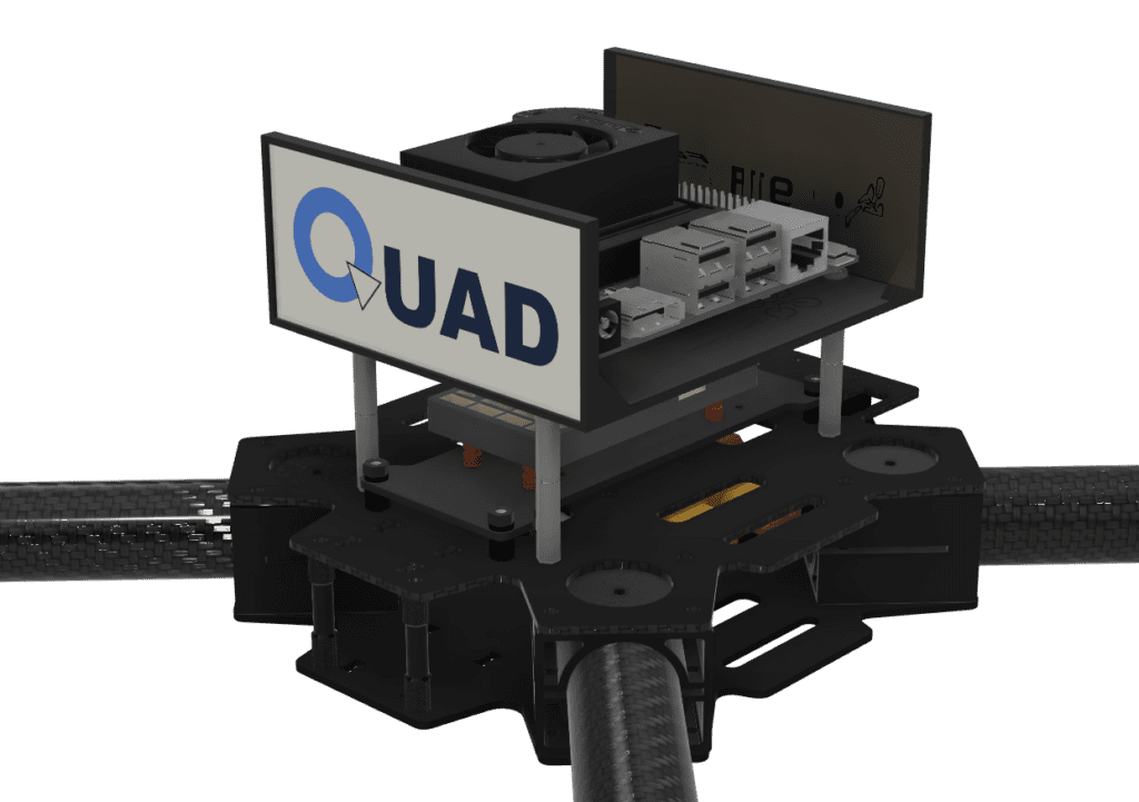
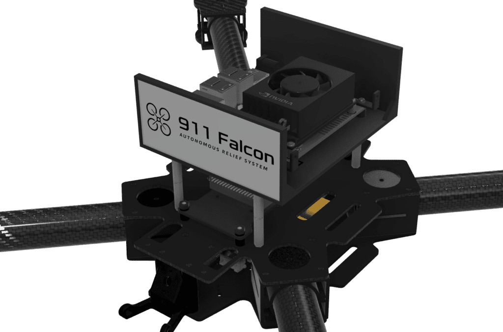
When designing the dedicated NVIDIA Jetson Orin Nano mount, the first points we considered were that the mount had to secure the Wi-Fi antennas connected to the Jetson Orin Nano and also provide a structure through which the CSI cable for the camera connection could be routed. Therefore, the mount could not simply be a structure for fixing the board alone. Instead, it required a geometry that could also incorporate both the antenna mounting structure and the cable passage as part of the design.
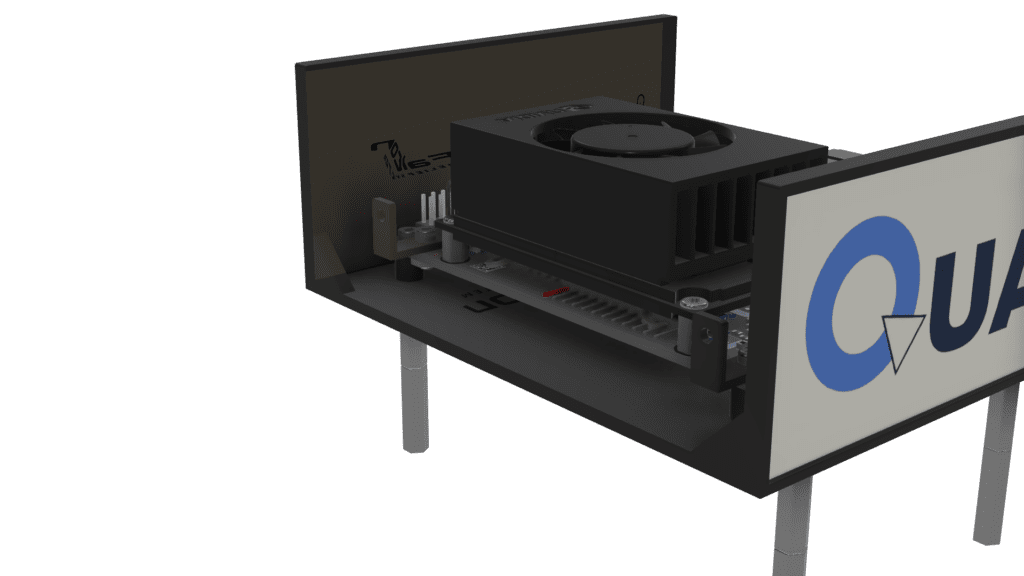
In addition, because the frame did not provide suitable mounting holes for directly installing the Jetson Orin Nano, the mount was designed by using the motor fastening holes to install standoffs, and then bolting the Jetson Orin Nano mount on top of them. This approach made it possible to utilize the upper space of the frame while mounting the computing unit in a separate and clearly defined structure from the other major components.
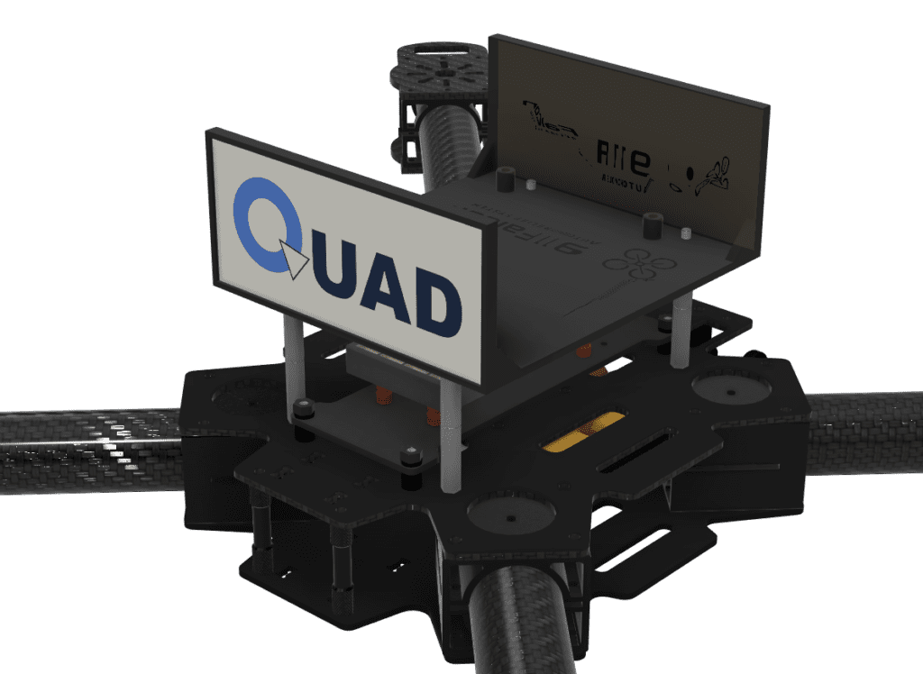
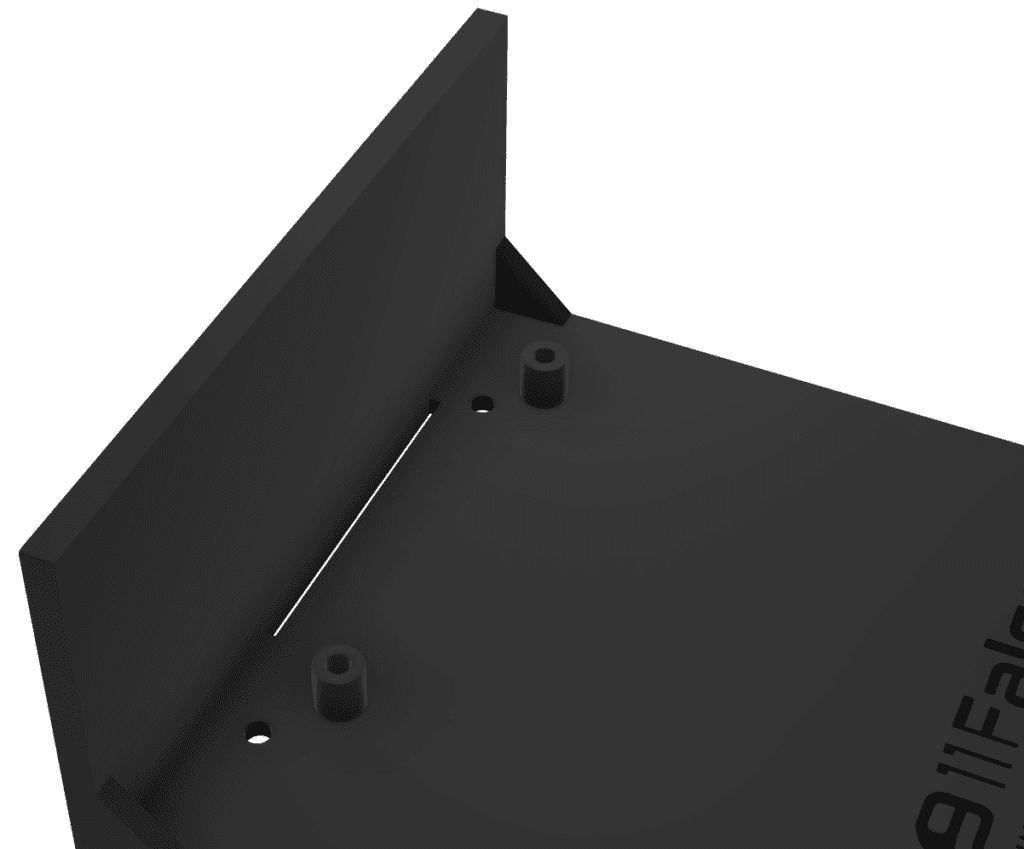
In addition, flat mounting surfaces were incorporated at the front and rear of the mount so that the QUAD logo and the project logo could be attached. Therefore, this Jetson Orin Nano mount was designed by considering not only board installation, but also Wi-Fi antenna fixation, the CSI cable passage, and the logo attachment surfaces as part of a single integrated structure.
1-4) ESC Mount Design
Product :
XRotor PRO 60A ESC

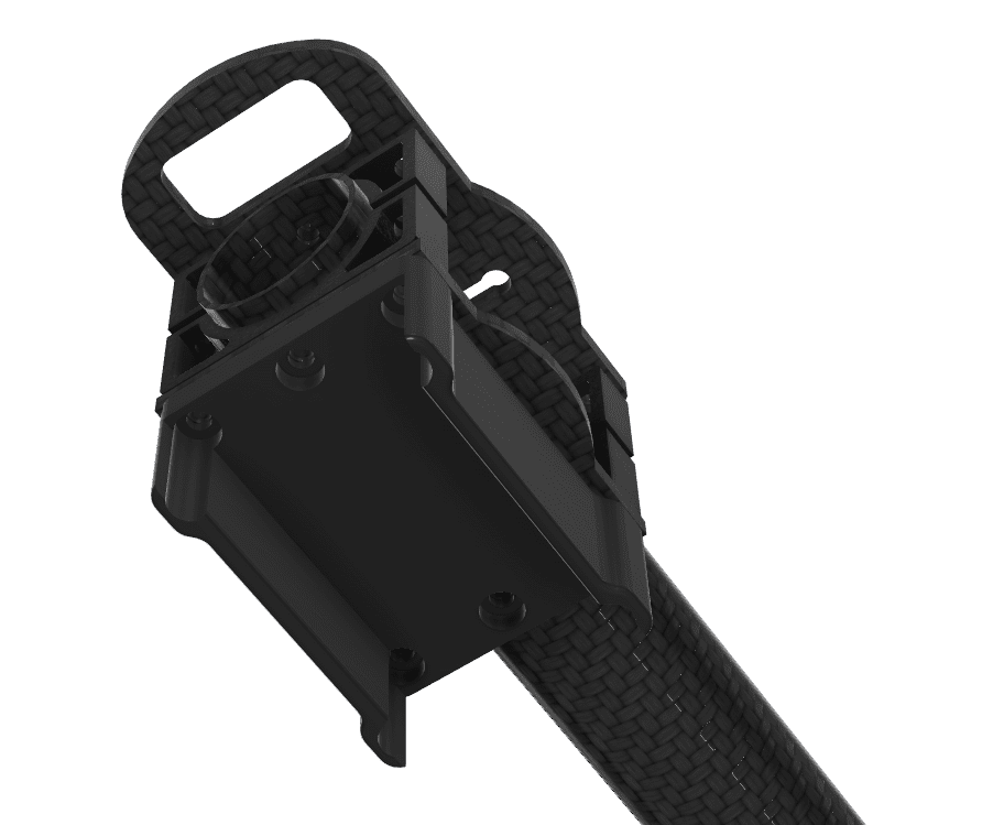
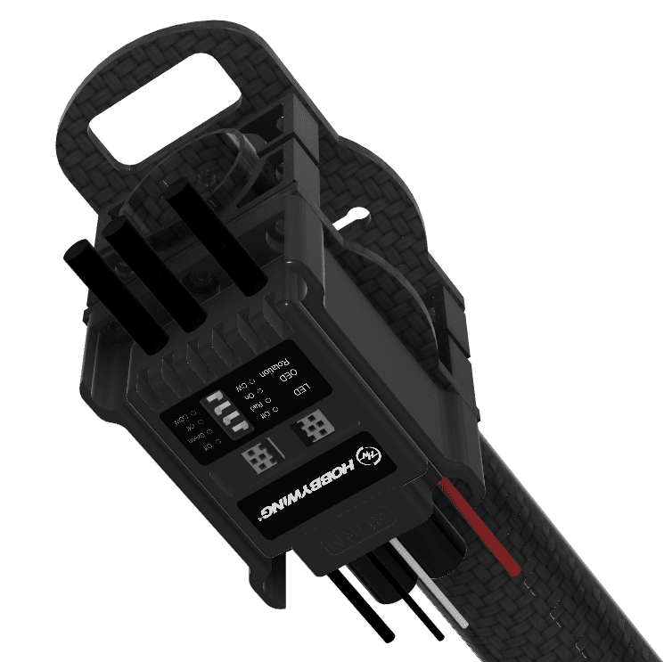
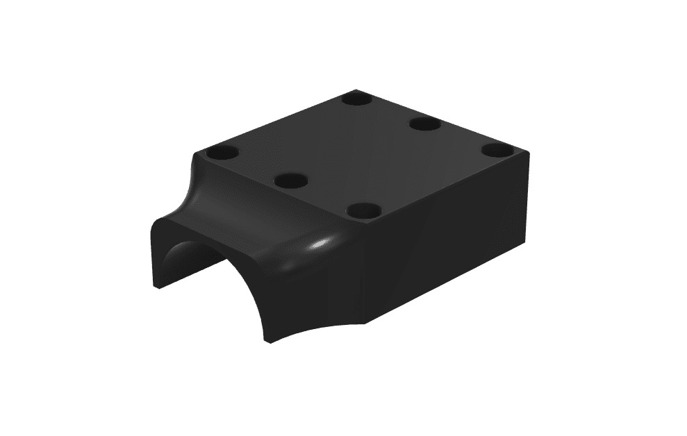
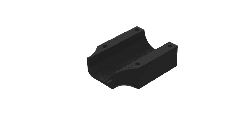
When designing the dedicated ESC mount, the first points we considered were that the ESC had to be positioned beneath each motor mount, while still maintaining good connectivity with the motor and allowing heat to dissipate efficiently. Because the ESC handles high current, it needed to be placed close to the motor, but at the same time, the structure had to allow airflow rather than being completely enclosed.
However, the frame did not provide separate fastening holes for directly mounting the ESC, and the design had to secure the ESC safely without interfering with heat dissipation. In addition, introducing a completely independent fastening structure would have made the overall design more complex and increased the number of fastening components. Therefore, it was necessary to adopt a method that could be integrated with the existing motor mount fastening structure as much as possible.
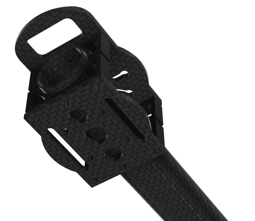
Therefore, the ESC mount was designed as a structure that is fastened together when the motor insert and motor mount are bolted. This made it possible to mount the ESC securely while minimizing the need for a separate independent fastening structure. In addition, the mount was designed with a partially open geometry rather than fully enclosing the ESC, allowing air to pass through and enabling air cooling. As a result, this ESC mount was designed as a structure that can be fastened together with the motor mount while still securing sufficient cooling performance.
1-5) Landing Gear Design
When designing the landing gear mount, the first points we considered were that the landing gear had to be attached to the arms, and that the design also needed to accommodate the possibility that the landing gear length could change in the future depending on modifications to the lower airframe structure. Therefore, rather than adopting a simple integrated structure tailored only to the current length, it was necessary to use a method that could respond more flexibly to future length adjustments and shape modifications.
However, the existing carbon arms did not provide dedicated holes for directly fastening the landing gear, which meant that immediate installation was not possible using the original frame structure alone. In addition, if the landing gear were designed as an overly simple structure, any future need for height adjustment or geometry changes would require the entire structure to be redesigned and manufactured again.
Therefore, the landing gear mount was first planned by adding fastening holes through direct drilling into the arms, and the overall structure was designed so that the upper mount, lower mount, and landing gear body would be bolted together as a single assembly. In theory, the upper mount and the lower mount with the landing gear could have been integrated into a simpler one-piece structure. However, considering the possibility of future landing gear length changes, we chose to adopt a separated modular design instead. As a result, this landing gear mount was designed not merely as a simple fixing part, but as an expandable mounting structure that also takes into account potential future changes to the lower airframe configuration.

In this article, we reviewed the design process for the dedicated mounts used for the major components of the 911 FALCON drone that required separate mounting structures. Each mount was designed not merely to fix a component in place, but with consideration for the limited internal space, interference with the existing frame, heat dissipation, vibration, wiring and cable routing, and even the possibility of future structural modifications.
In particular, the PDB and Power Module were arranged so that they could be accommodated together within the central stacked space, while the Pixhawk 6X mount was designed to resolve interference with the lower structure and at the same time incorporate a vibration isolation mechanism. The NVIDIA Jetson Orin Nano mount was developed as an upper-layer mounting structure that also reflected the routing requirements for the Wi-Fi antennas and the CSI cable, and the ESC and landing gear were likewise given dedicated structures based on their actual fastening methods and operational requirements.
In the next article, we will continue by covering how these dedicated mounts were actually applied to the airframe, along with the process of assembling the major components and arranging the remaining parts of the system. Thank you.

Author: Guenchan lee, Senior Researcher of QUAD Drone Lab.
Date: March 31, 2026
![[MAVSDK C++ Part 4] Building Your Own App: Project Setup and Drone Connection](https://quad-drone-lab.co.kr/wp-content/uploads/2026/03/0314_인포그래피-768x512.png)
![PX4 MAVSDK – C++ Programming [Episode 5] Querying System Information and Using Telemetry](https://quad-drone-lab.co.kr/wp-content/uploads/2026/03/0315_인포그래피-768x512.png)
![PX4 MAVSDK – C++ Programming [Episode 10] Custom Logging and Integration Testing (gtest)](https://quad-drone-lab.co.kr/wp-content/uploads/2026/03/0320_인포그래피-768x419.jpg)