Receiver Wiring and Setup : 911 FALCON Project
Hello, this is QUAD Drone Laboratory.
I’m Geunchan Lee, Senior Researcher at QUAD Drone Lab.
In the previous article, we covered the overall power supply flow of the 911 FALCON drone’s electrical system. We confirmed the structure in which power is supplied to each component, divided into the FC circuit and PDB circuit based on the power module.
In this article, we will cover the receiver wiring and setup process. We will go through the process in order — from transmitter configuration, to receiver wiring, firmware update, and binding, and finally FC parameter settings, RC calibration, and flight mode configuration.
1. Transmitter Configuration
1-1) ELRS Version Check

First, check the ELRS version installed on the Jumper T20 transmitter. Since ELRS requires the firmware versions of the transmitter and receiver to match in order to bind, it is recommended to check and record the current version of the transmitter before proceeding with the receiver firmware update.
1-2) Channel Setup
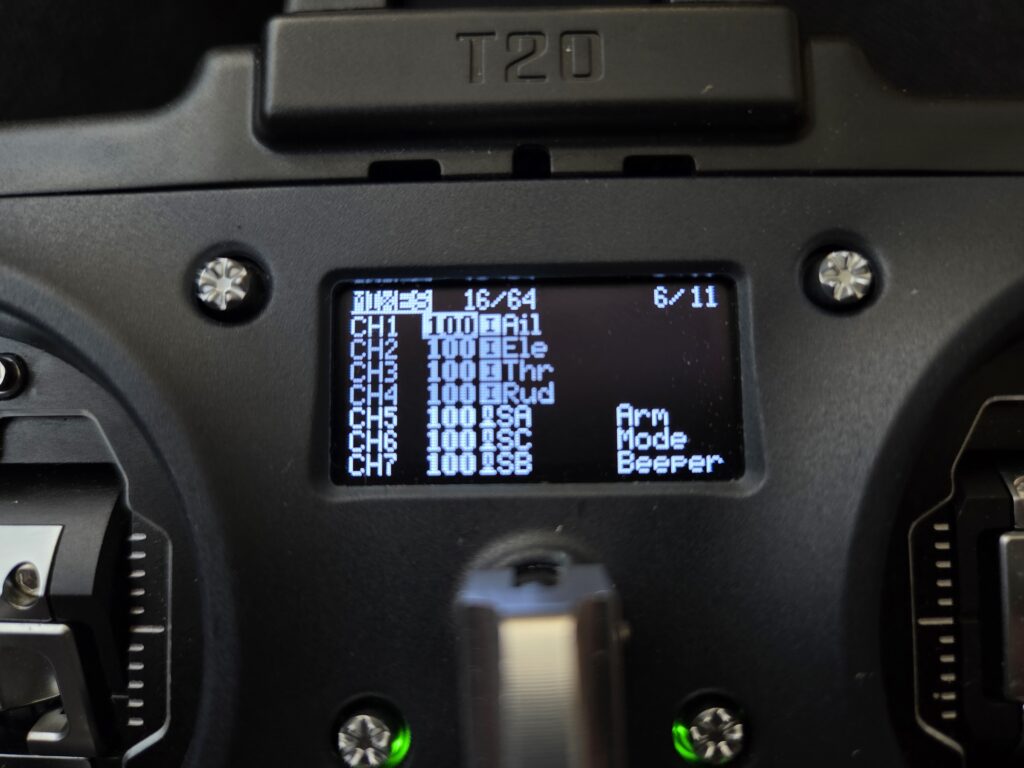
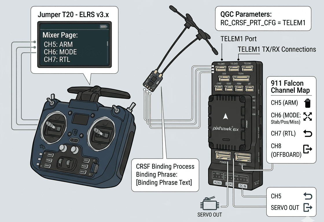
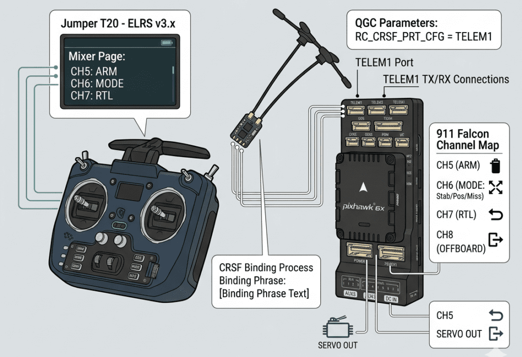
Each switch must be assigned to a channel on the transmitter’s Mixer page. Without this configuration, the switches will have no channel assigned, meaning that no matter how carefully the flight modes are set up in QGroundControl (QGC), the switches will not function correctly. Therefore, channel assignment in the Mixer page must be completed before moving on to FC configuration.
2. Receiver
2-1) Wiring
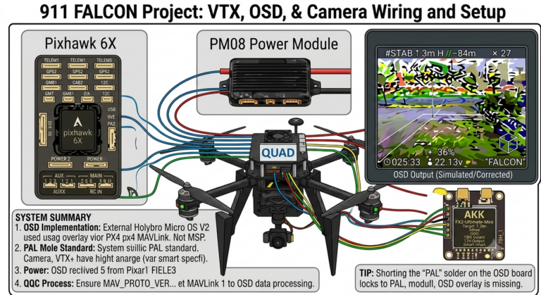
The Radiomaster RP3 receiver is wired through the TELEM1 port of the Pixhawk 6X FC. While the Pixhawk 6X has a dedicated RC IN port that supports SBUS receivers, ELRS receivers using the CRSF protocol cannot be connected through that port. The receiver is therefore wired through the TELEM1 port, and the port must be designated as the receiver input through parameter settings afterward.
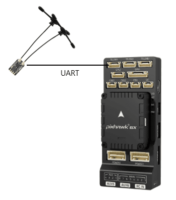
When wiring, the characteristics of UART communication must be taken into account. Since UART operates by cross-connecting the transmit (TX) and receive (RX) lines, the receiver’s RX must be connected to the TX of the TELEM1 port, and the receiver’s TX must be connected to the RX of the TELEM1 port. Power is supplied by connecting the 5V and GND lines in the correct polarity between the receiver and the TELEM1 port.
2-2) Binding
There are three main methods for binding an ELRS receiver to a transmitter.
(1) Binding Mode via Power Cycling
With the transmitter powered off, plug and unplug the receiver’s power connector three times in succession to enter binding mode. When binding mode is active, the LED will flash twice rapidly (quick double blink). After that, select Bind from the ELRS LUA script on the transmitter to complete binding. Note that this method only works when no binding phrase is set on the receiver — if a binding phrase has already been configured, this method cannot be used. Additionally, the firmware versions of the transmitter and receiver must match; binding will not occur if the versions differ, so version verification is essential beforehand.
(2) Binding Phrase Input via Web UI
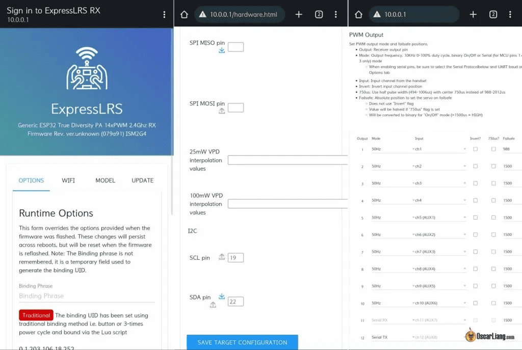
After powering on the receiver, it will automatically enter WiFi mode after 60 seconds. When in WiFi mode, the LED will flash rapidly. Connect your laptop or smartphone to the “ExpressLRS RX” WiFi hotspot created by the receiver, then enter the binding phrase directly in the OPTION menu of the Web UI and execute Save & Reboot to complete binding. This method is convenient as it allows the binding phrase to be set without flashing firmware, but requires V3 firmware or later.
(3) Setting Binding Phrase via Firmware Flashing
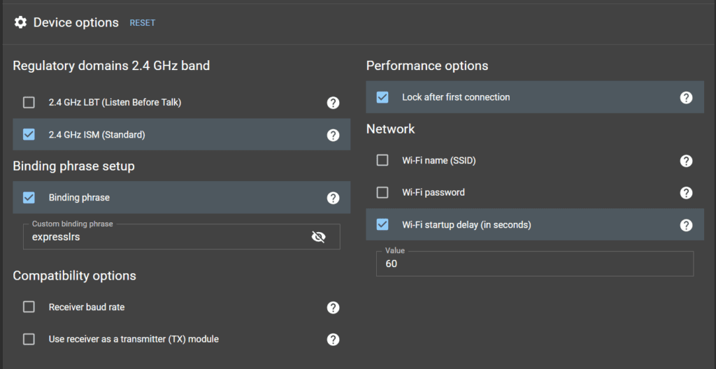
Install ELRS Configurator on your computer and Build the firmware for both the transmitter and receiver within the Configurator. During this process, enter the binding phrase along with the build settings, then update the built firmware to both the transmitter and receiver to complete binding. This method is efficient as it allows firmware update and binding to be performed simultaneously.
For the 911 FALCON, since the receiver firmware needed to be updated to match the transmitter version, method (3) Setting Binding Phrase via Firmware Flashing was adopted, allowing the firmware update and binding to be completed in a single step.
3. FC Configuration
3-1) Parameter Settings
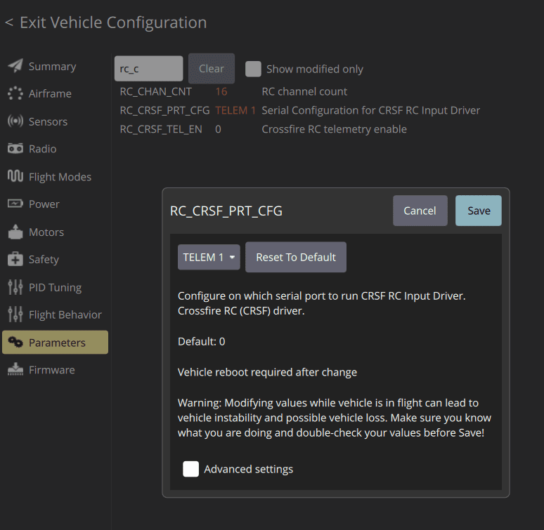
In QGroundControl (QGC)‘s Parameters tab, the RC_CRSF_PRT_CFG parameter must be set to TELEM1. This setting allows the FC to recognize the TELEM1 port as the CRSF receiver input port. Without this parameter configured, the FC will not be able to receive the receiver’s signal correctly, so parameter configuration must be completed first after wiring.
3-2) RC Calibration
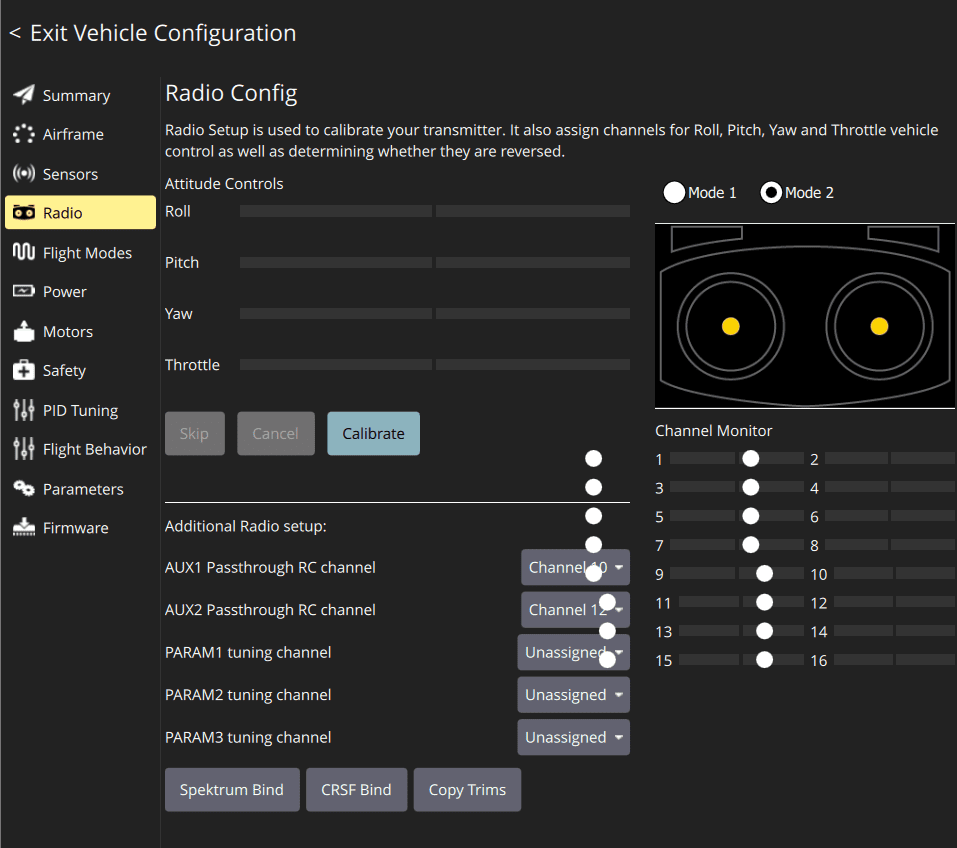
RC calibration is performed in QGC‘s Radio tab. Through calibration, the minimum and maximum values of each stick and the position of each switch are saved to the FC. This process allows the FC to accurately recognize the input range of the transmitter.
3-3) Flight Mode Configuration
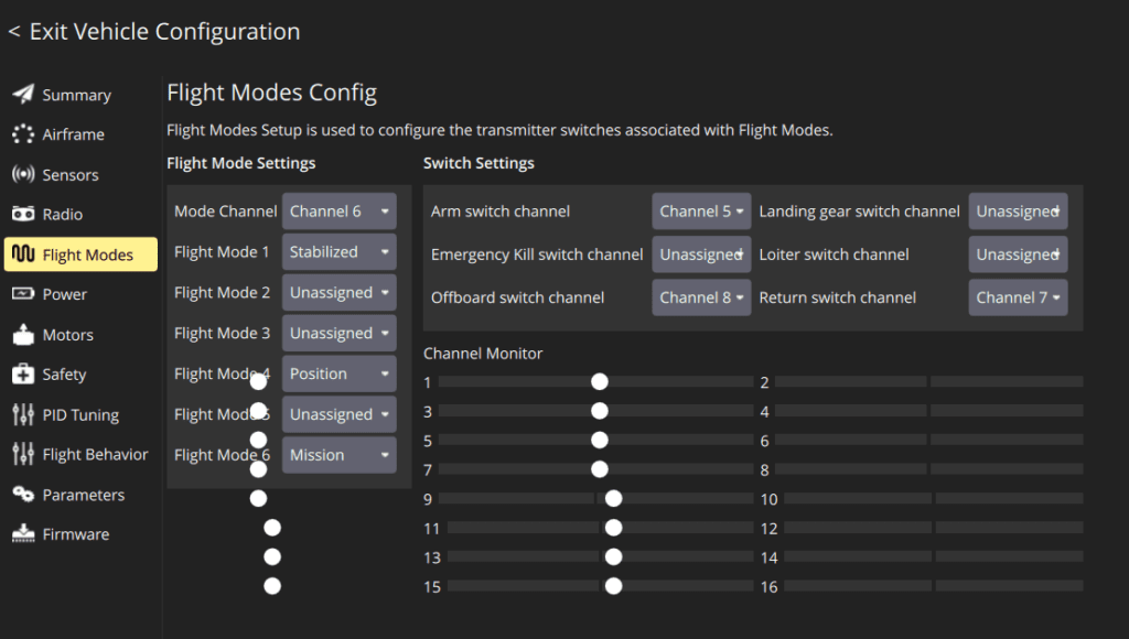
Flight modes are configured in QGC‘s Flight Modes tab. After operating each switch in the Radio tab to confirm which channel it is assigned to, the desired function is set for each position.
The 911 FALCON was configured with the following channel assignments:
- Channel 5 — Arming switch, controls motor start
- Channel 6 — 3-position toggle switch, cycles through Stabilized → Position → Mission modes
- Channel 7 — Return mode, enables immediate return-to-home from the transmitter
- Channel 8 — Offboard mode, enables switching to external computer control
This configuration ensures that all flight functions required for mission execution can be controlled directly from the transmitter.
This article covered the receiver wiring and setup process for the 911 FALCON drone. Starting from transmitter channel configuration and ELRS version verification, we proceeded through receiver wiring, firmware update, and binding, followed by FC parameter settings, RC calibration, and flight mode configuration.
In the next article, we will cover the motor and ESC wiring process based on the receiver setup completed in this article. We will go through the wiring between the ESC and motors, power connection to the PDB, signal wire connections to the FC, and confirm arming and throttle operation via the transmitter. Thank you for reading.

Author: Guenchan lee, Senior Researcher of QUAD Drone Lab.
Date: May 15, 2026
![[ROS2 Mastery Part 3] A Guide to Creating Your First ROS2 Package and Programming a Python Node](https://quad-drone-lab.co.kr/wp-content/uploads/2026/05/0507_인포그래픽-768x512.png)
![[Hybrid Navigation System: Part 3 Hardware & Modeling] A Deep Dive into Industrial High-Performance INS & Making GPS Jamming Simulator](https://quad-drone-lab.co.kr/wp-content/uploads/2026/04/Physics-of-IMU-Drift-Errors-768x429.jpg)
![PX4 MAVSDK – C++ Programming [Episode 6] Basic Flight Control using Action API](https://quad-drone-lab.co.kr/wp-content/uploads/2026/03/0316_인포그래피-768x512.png)