

Drone Component Selection – Power System : 911 FALCON Project
Hello, this is QUAD Drone Laboratory.
I’m Geunchan Lee, Senior Researcher at QUAD Drone Lab.
In the previous post, I introduced the propulsion system selection process for the 911 FALCON drone. Using the mission requirements as fixed KPIs, I explained how the frame and propeller class, target AUW, motor, ESC, and battery were progressively refined through an iterative design approach.
In this post, I’ll cover the next subsystem in the series: the power system. This part focuses on how the battery, power module, and PDB were selected, and how power is distributed across the drone to support stable system operation.
Power System Design Objectives
At the outset, we first defined the mission requirements.
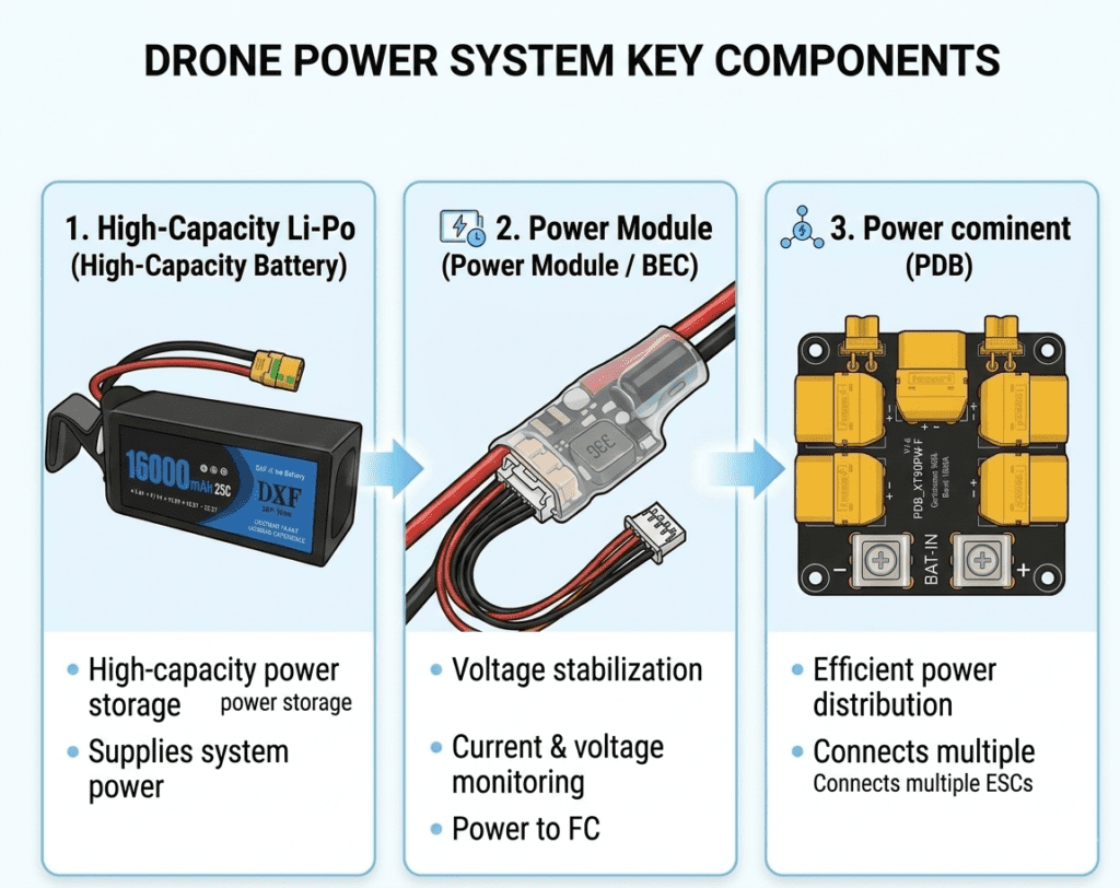
The power system of the 911 FALCON is not simply a structure for “delivering electricity,” but one that must satisfy the following requirements simultaneously:
- Provide stable high-current power to the propulsion system (motors and ESCs)
- Enable the flight controller (FC) to accurately monitor battery status
- Ensure reliability and maintainability of the power architecture throughout repeated operation cycles (return → landing → redeployment)
In other words, the core objective of this power system design is to integrate the following into a single architecture:
Battery → Power Distribution → Voltage/Current Monitoring → Stable Power Supply to Each Device
STEP 1 : Battery Selection
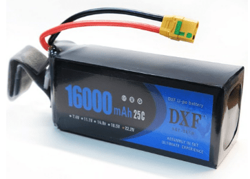
For this airframe, the design was converged around a 6S voltage architecture during the propulsion system selection process. In the previous step, the target battery weight was also set in the range of approximately 1.60–2.01 kg. Based on these constraints, the candidate battery capacity range was reviewed within 6S 16Ah to 22Ah.
Key Specifications
- Dimensions: 185 × 76 × 66 mm
- Voltage: 22.2 V (6S)
- Capacity: 16,000 mAh
- Discharge Rate: 25C
- Connector: XT90
- Weight: Approx. 2,000 g
Reason for Selecting the 16,000 mAh Battery:
Although the candidate capacity range was set between 16 Ah and 22 Ah, the final selection was not made by simply choosing “the battery with the largest capacity.” This is because flight endurance is influenced not only by battery capacity, but also by AUW (All-Up Weight) and hover efficiency (W/kg).
A 22,000 mAh-class battery can theoretically provide longer endurance. However, its increased mass also raises the AUW, which in turn increases the hover power requirement. In other words, increasing battery capacity does not necessarily translate directly into longer flight time.
In contrast, the 6S 16,000 mAh battery, at approximately 2.0 kg, is well aligned with the target battery weight range established in the previous step. Therefore, in this design, the 16 Ah-class battery was selected as the baseline option, with a strategy to validate actual hover power and W/kg during flight testing and expand to a higher-capacity pack later if necessary.
STEP 2 : Power Module Selection
The power module is responsible for supplying stable power from the battery to the flight controller (FC), while also measuring battery voltage and current. In the overall power architecture, the ESC drive power is distributed through the PDB, while the power module serves as the power management layer dedicated to FC power supply and power monitoring.

Power Module Selection Criteria
The propulsion system of this airframe is configured with MN5212 KV420 motors paired with 15-inch propellers. Based on bench test data, the maximum current per motor is approximately 36.7 A, which means that under a quadcopter configuration, the total current can rise to over 140 A in the maximum-throttle region.
Therefore, the power monitoring device must provide a sufficient current measurement range and stable power delivery to ensure reliable operation under this electrical load environment.
Holybro PM02D Power Module
- Support for a 6S battery voltage architecture
- A 6-pin power interface compatible with Pixhawk-series flight controllers
- Support for voltage and current monitoring based on flight logs
These features make it a suitable choice for the power architecture and operational requirements of this airframe.
The power module is not merely a component for power delivery, but also a measurement device that serves as the basis for flight stability and threshold-based safety logic. This is because the flight controller must accurately recognize voltage and current values in order for functions such as low-voltage warnings, RTL activation, and failsafe return logic to operate reliably within the configured voltage thresholds.
STEP 3 : PDB(Power Distribution Board) Selection
The PDB is responsible for distributing the main battery power stably to each ESC while also organizing the high-current internal wiring in a structured manner. Since this airframe was designed around a 15-inch-class propulsion system, a board-based power distribution structure was considered more appropriate than simple parallel wiring for handling high-current power delivery. Accordingly, the 911 FALCON adopts a PDB (Power Distribution Board) to configure the ESC power distribution system.

PDB Selection Criteria
The maximum current per motor for this airframe is approximately 36.7 A. Accordingly, under a quadcopter configuration, the total maximum current at full throttle is estimated to be around 140 A. Considering additional operational factors such as heat generation, environmental variation, and transient peak current, an operating margin of 1.3 to 1.5 was applied. Based on this, the power distribution structure was determined to require the capability to handle at least approximately 210 A or more in a stable manner.
In addition, the main power architecture of this airframe was designed around an XT90 platform, while auxiliary devices also needed to be supported through XT30-based secondary power outputs. Taking these requirements into account, the Holybro 300A PDB was selected as the final choice, as it provides sufficient current headroom and an appropriate power distribution structure for this system.
STEP 4: Power Supply Architecture for Each Device
The final step of the power system design is to clearly define how power is delivered to each device through the overall architecture. For this airframe, the power distribution structure was organized as follows for the FC, ESCs, VTX, and Jetson Orin Nano.
4-1) FC (Flight Controller)
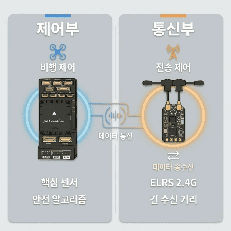
The Pixhawk 6X flight controller receives power through the 6-pin power connector of the power module.
This structure allows the FC power supply to be separated from the ESC drive power path, which helps reduce the effects of electrical noise and improves the accuracy of battery voltage and current monitoring. In addition, the FC uses the battery data measured through the power module to execute safety functions such as low-voltage warnings, RTL, and fail-safe logic.
4-2) ESC
The ESCs receive main battery power distributed through the PDB.
In this structure, the main power from the battery is first fed into the PDB and then distributed to each ESC. This allows all four ESCs to receive the high-current power they require in a stable manner, while also making the overall power architecture more organized. For an airframe like this one, which uses a 15-inch-class propulsion system, it was considered more reliable to structure the ESC power distribution around a PDB rather than using a simple parallel wiring configuration.
4-3) VTX (Video Transmitter)
4-3) VTX (Video Transmitter)
The video transmitter (VTX) is not powered directly from the main battery voltage. Instead, its power is supplied through a structure in which the voltage is first stepped down by a BEC, and then delivered through the OSD module.
The power flow is as follows:
Battery / PDB main power → BEC (24V → 9V) → OSD module → VTX
This structure was adopted to provide the VTX with a separately regulated voltage suitable for stable operation, while also organizing its integration with the OSD module into a single power path. In other words, the video transmission system was not designed as a simple direct power connection, but as a structured path in which the voltage is first conditioned and then delivered to the transmitter through the OSD module for stable operation.
4-4) Jetson Orin Nano
The Jetson Orin Nano, which handles onboard computing, cannot be powered directly from the battery voltage. Therefore, its power supply was configured through a structure in which the battery voltage is stepped down by a UBEC before being delivered to the device.
The power flow is as follows:
Battery (6S) → UBEC → Jetson Orin Nano
This approach converts the high voltage of the 6S battery into the stable low voltage required by the Jetson, ensuring reliable operation of the onboard vision and streaming system. Since the Jetson is directly involved in downward camera streaming and precision landing verification, it was important to separate its power supply into an independent and stable power path.
Power System Architecture Summary
The power architecture of this airframe can be summarized as follows.

Battery → Power Module → Power Distribution PDB → ESCs → Motors
↓ ↓ ↓
FC Video System Jetson Orin Nano
In this post, we reviewed the power system selection process for the 911 FALCON drone. The overall power architecture can be understood as a structure in which power is distributed from the battery to each device according to its specific electrical requirements. Through this approach, the propulsion system, flight controller, video transmitter, and onboard computing device were configured to operate reliably under the voltage conditions each subsystem requires.
In the following post, we’ll focus on the communications and control subsystem including the FC, GPS, receiver, Jetson, and link configuration and explain how flight control and data flow were integrated into a cohesive system architecture.
Thank you.

Author: Guenchan lee, Senior Researcher of QUAD Drone Lab.
Date: March 09, 2026
![PX4 MAVSDK – C++ Programming [Episode 10] Custom Logging and Integration Testing (gtest)](https://quad-drone-lab.co.kr/wp-content/uploads/2026/03/0320_인포그래피-768x419.jpg)
![PX4 MAVSDK – C++ Programming [Part 9] Precision Drone Control: Offboard Mode](https://quad-drone-lab.co.kr/wp-content/uploads/2026/03/0319_인포그래픽-768x429.jpg)
![PX4 MAVSDK – C++ Programming [Episode 7] Moving to a Specific Location (goto_location) and Understanding the Haversine Formula](https://quad-drone-lab.co.kr/wp-content/uploads/2026/03/0317_인포-768x512.png)
![[PX4 Tuning Series 7] Land Detector Configuration: The Essential Guide for a Perfect Flight Conclusion](https://quad-drone-lab.co.kr/wp-content/uploads/2026/03/Drone-Ground-Contact-Landing-Logic-768x429.png)
![PX4 MAVSDK – C++ Programming [Episode 6] Basic Flight Control using Action API](https://quad-drone-lab.co.kr/wp-content/uploads/2026/03/0316_인포그래피-768x512.png)