
[PX4 ROS 2 Programming] Part 4: Offboard Control (Drone Position and Trajectory Control)
Hello again, university students and researchers pioneering autonomous flight robotics! It is great to have you back.
In Part 3, we tested our communication network by writing basic Listener (Subscriber) and Advertiser (Publisher) nodes to exchange data between ROS 2 and PX4. Now that we have confirmed the system’s pulse is beating steadily, it is finally time to take over the drone’s “brain” and make it move exactly how we want.
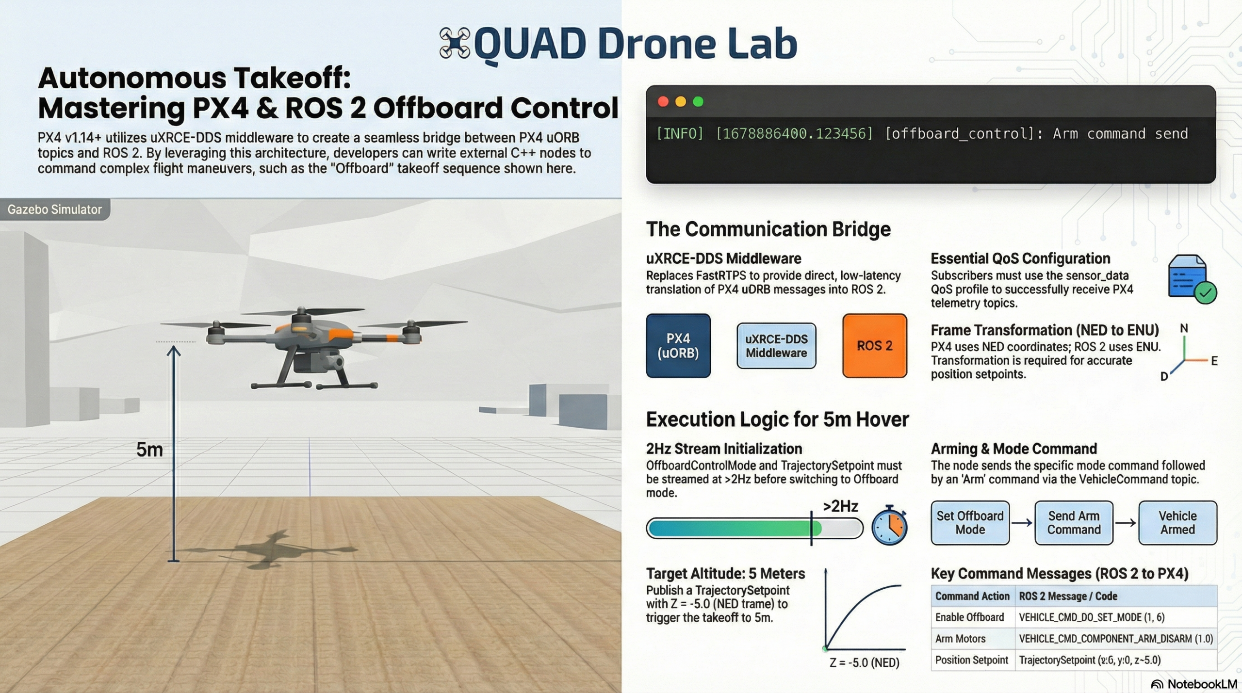
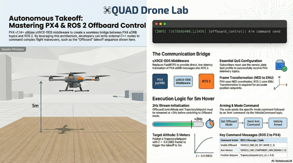
In this Part 4, we will dive into the absolute core and highlight of drone programming: Offboard Control mode. We will implement the entire sequence of arming the drone and making it take off to a specific coordinate (5 meters in altitude) to hover,.
1. What is Offboard Control?
Normally, drones are controlled by moving the sticks on a remote controller (RC). However, for autonomous flight, a companion computer must replace the RC and send target position, velocity, or thrust commands to the flight controller (PX4). This flight mode, where an external computer or a ROS 2 node directly issues flight commands, is called ‘Offboard mode’.
🚨 The Key to Entering Offboard Mode: The “2Hz Heartbeat”
In actual flight, Offboard control can be highly dangerous. If your code crashes and the drone stops receiving control commands, it could lead to a severe accident.
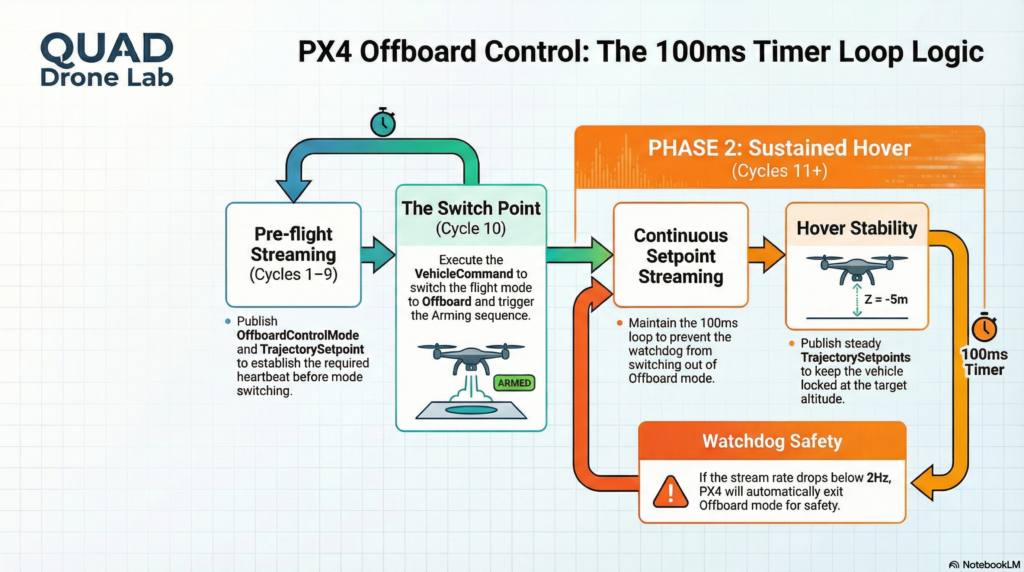
Therefore, the PX4 system demands very strict failsafe conditions. For PX4 to switch to Offboard mode and allow arming, OffboardControlMode and TrajectorySetpoint messages must be continuously streamed at a rate of at least 2Hz (twice per second) before the mode switch occurs,. If the stream rate of these messages drops below approximately 2Hz during flight, PX4 will immediately switch out of offboard mode and force a failsafe action (e.g., hovering in place or landing).
2. Writing the Offboard Control Node
Now, let’s write a C++ ROS 2 node that commands the drone to take off to an altitude of 5 meters and rotate its heading (Yaw) by 180 degrees. To satisfy the “heartbeat” condition explained above, we will construct our main loop using a 100ms (10Hz) timer,.
The overall code is divided into publishing three main types of messages:
- OffboardControlMode: Informs PX4 of the type of offboard control being used (e.g., position control, velocity control).
- TrajectorySetpoint: Provides the target coordinates (X, Y, Z) and heading (Yaw).
- VehicleCommand: Sends commands to the flight controller to switch to Offboard mode and arm the vehicle.
Below is the complete example code (offboard_control.cpp) that includes all of these elements. Read through it carefully.
#include <rclcpp/rclcpp.hpp>
#include <px4_msgs/msg/offboard_control_mode.hpp>
#include <px4_msgs/msg/trajectory_setpoint.hpp>
#include <px4_msgs/msg/vehicle_command.hpp>

using namespace std::chrono_literals;

class OffboardControl : public rclcpp::Node
{
public:
    OffboardControl() : Node("offboard_control")
    {
        // Create Publishers
        offboard_control_mode_publisher_ = this->create_publisher<px4_msgs::msg::OffboardControlMode>("/fmu/in/offboard_control_mode", 10);
        trajectory_setpoint_publisher_ = this->create_publisher<px4_msgs::msg::TrajectorySetpoint>("/fmu/in/trajectory_setpoint", 10);
        vehicle_command_publisher_ = this->create_publisher<px4_msgs::msg::VehicleCommand>("/fmu/in/vehicle_command", 10);

        // Setup a 100ms (10Hz) timer callback
        auto timer_callback = [this]() -> void {

            // For the first 10 cycles (1 second), we only publish setpoints to prepare PX4.
            if (offboard_setpoint_counter_ == 10) {
                // After 10 setpoints have been sent, we change the mode to Offboard and arm.
                this->publish_vehicle_command(px4_msgs::msg::VehicleCommand::VEHICLE_CMD_DO_SET_MODE, 1, 6);
                this->arm();
            }

            // Publish the control mode and trajectory setpoint every cycle (Must maintain > 2Hz)
            publish_offboard_control_mode();
            publish_trajectory_setpoint();

            if (offboard_setpoint_counter_ < 11) {
                offboard_setpoint_counter_++;
            }
        };

        timer_ = this->create_wall_timer(100ms, timer_callback);
    }

    void arm()
    {
        publish_vehicle_command(px4_msgs::msg::VehicleCommand::VEHICLE_CMD_COMPONENT_ARM_DISARM, 1.0, 0.0);
        RCLCPP_INFO(this->get_logger(), "Arm command send");
    }

private:
    rclcpp::TimerBase::SharedPtr timer_;
    rclcpp::Publisher<px4_msgs::msg::OffboardControlMode>::SharedPtr offboard_control_mode_publisher_;
    rclcpp::Publisher<px4_msgs::msg::TrajectorySetpoint>::SharedPtr trajectory_setpoint_publisher_;
    rclcpp::Publisher<px4_msgs::msg::VehicleCommand>::SharedPtr vehicle_command_publisher_;

    uint64_t offboard_setpoint_counter_ = 0;

    // Set control mode (Enable Position Control)
    void publish_offboard_control_mode()
    {
        px4_msgs::msg::OffboardControlMode msg{};
        msg.position = true;      // Position control active
        msg.velocity = false;
        msg.acceleration = false;
        msg.attitude = false;
        msg.body_rate = false;
        msg.timestamp = this->get_clock()->now().nanoseconds() / 1000;
        offboard_control_mode_publisher_->publish(msg);
    }

    // Command target coordinates (Altitude 5m, Yaw 180 degrees)
    void publish_trajectory_setpoint()
    {
        px4_msgs::msg::TrajectorySetpoint msg{};
        // IMPORTANT: PX4 uses the NED (North-East-Down) frame, so Z-axis -5.0 means 5m up!
        msg.position = {0.0, 0.0, -5.0};
        msg.yaw = -3.14; // [-PI:PI] range (approx. -180 degrees)
        msg.timestamp = this->get_clock()->now().nanoseconds() / 1000;
        trajectory_setpoint_publisher_->publish(msg);
    }

    // Send MAVLink commands to the flight controller
    void publish_vehicle_command(uint16_t command, float param1, float param2)
    {
        px4_msgs::msg::VehicleCommand msg{};
        msg.param1 = param1;
        msg.param2 = param2;
        msg.command = command;
        msg.target_system = 1;
        msg.target_component = 1;
        msg.source_system = 1;
        msg.source_component = 1;
        msg.from_external = true;
        msg.timestamp = this->get_clock()->now().nanoseconds() / 1000;
        vehicle_command_publisher_->publish(msg);
    }
};

int main(int argc, char *argv[])
{
    rclcpp::init(argc, argv);
    rclcpp::spin(std::make_shared<OffboardControl>());
    rclcpp::shutdown();
    return 0;
}
3. Breaking Down the Core Code
While the code might look a bit long, it is clearly divided into functional units. Let’s walk through the core concepts every researcher must grasp.
1) The Initial 1-Second (10 Cycles) Wait Logic in timer_callback
As explained earlier, PX4 requires that the vehicle is already receiving OffboardControlMode messages before it will switch to offboard mode. Therefore, the loop runs on a 100ms timer, and for the first 10 cycles (100ms * 10 = 1 second), it simply streams the control mode and setpoints to PX4. This makes PX4 realize, “Ah, stable external commands are coming in!” After 10 cycles, publish_vehicle_command() is called to change the mode, and arm() is called to arm the vehicle.
2) publish_offboard_control_mode()
Since we want to control the drone by commanding a specific position, we set the position field to true and all the other fields (like velocity, acceleration, and attitude) to false. This message acts as an indicator to inform PX4 of the ‘type’ of control being used.
3) publish_trajectory_setpoint() and Coordinate Frame Warning
This is the part where many researchers get confused when running simulations for the first time. We set msg.position = {0.0, 0.0, -5.0}, making the Z value negative. Why put -5.0 when we want to go 5 meters UP? Remember the Coordinate Frames we covered in Part 2! While ROS 2 uses the ENU (East-North-Up) system where “Up” is positive, PX4 adopts the FRD (NED) conventions on all topics unless explicitly specified. In the NED (North-East-Down) frame, the positive (+) Z-axis points ‘Down’. Thus, this example publishes positions in the NED frame as expected by PX4, meaning you must input -5.0 to fly 5 meters up.
4) publish_vehicle_command()
The VehicleCommand message is one of the simplest and most powerful ways to command PX4 (e.g., Takeoff, Land, Arm, Mode Change). Internally, the param and command fields map directly to MAVLink MAV_CMD codes and their parameter values.
4. Running the Node and Verifying in Simulation
If you have successfully written the code, let’s build the workspace and run it.
Open a terminal and build the code:
cd ~/ws_offboard_control/
source /opt/ros/humble/setup.bash
colcon build
- Make sure the Micro XRCE-DDS Agent and the PX4 Gazebo simulator are running in other terminals. (Tip: Make sure that QGroundControl (QGC) is connected to PX4 before running the ROS 2 node. By default, you cannot arm a vehicle without a connection to a ground station to ensure there is always an option to regain manual control.)
- Source the built workspace and run the node:
source install/local_setup.bash
ros2 run px4_ros_com offboard_control
When the node runs, you will witness the thrilling sight of the drone in the simulator spinning its propellers (Arming), ascending forcefully into the sky, and stopping exactly at an altitude of 5 meters to hover,! Furthermore, while the code is running, the vehicle’s heading (Yaw) will rotate to and maintain a 180-degree angle.
Wrapping Up
Congratulations! Through this Part 4, you have grasped the underlying principles of Offboard control—the heart of autonomous drone flight—and successfully taken control of the vehicle’s position using a C++ node. As long as you remember the safety net logic of the 100ms timer and the trap of the NED coordinate frame,, you can easily integrate any complex trajectory generation algorithm based on your brilliant ideas into this framework.
In the upcoming Part 5: Advanced Techniques (Service Servers and Multi-Vehicle Simulation), we will go beyond simply publishing messages. We will explore the VehicleCommand Service communication technique to reliably receive an “acknowledgment” that an arming command was successful, and we will cover Multi-Vehicle simulation methods to control a swarm of drones using a single companion computer.
If you have any questions, please feel free to leave a comment. Best of luck with your research and projects, and see you in the next part!
YouTube Class

Author: maponarooo, CEO of QUAD Drone Lab
Date: February 28, 2026
![PX4 MAVSDK – C++ Programming [Part 12] Advanced Autonomous Flight Research Cases Using MAVSDK C++](https://quad-drone-lab.co.kr/wp-content/uploads/2026/03/0322_인프그래피2-768x429.jpg)
![ROS2 Mastery [Part 1] Complete Guide to ROS2 Jazzy Development Environment and Workspace](https://quad-drone-lab.co.kr/wp-content/uploads/2026/03/0330_인포그래픽-1-768x429.png)
![PX4 MAVSDK – C++ Programming [Episode 10] Custom Logging and Integration Testing (gtest)](https://quad-drone-lab.co.kr/wp-content/uploads/2026/03/0320_인포그래피-768x419.jpg)
![[Everything About Drone Batteries] Part 1: Drone Battery Fundamentals and Chemical Characteristics: LiPo vs. Li-Ion](https://quad-drone-lab.co.kr/wp-content/uploads/2026/04/Drone-Battery-Anatomy-and-Assembly-768x429.jpg)