
Drone Component Selection – Propulsion System : 911 FALCON Project
Hello, this is QUAD Drone Laboratory.
I’m Geunchan Lee, Senior Researcher at QUAD Drone Lab.
In Week 2, I organized the communication system architecture of 911 FALCON, including the GPS-based return-destination update structure.
Starting from Week 3, before moving into fabrication, I’ll document the airframe component selection process by subsystem.
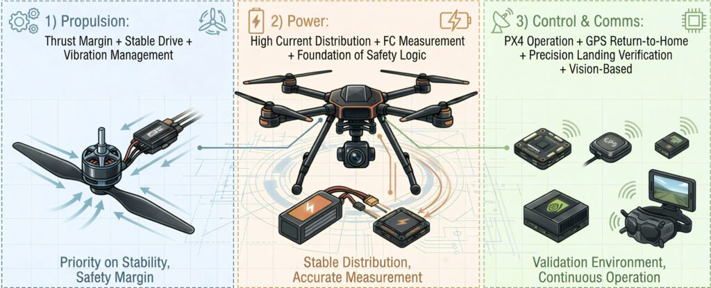
Since it’s too extensive to cover in a single post, this series will be published in three parts: Propulsion → Power → Control & Communications.
In this post—the first part—I’ll focus on the propulsion system (motor, ESC, propeller, and battery) and summarize the selection process through iterative refinement (iteration).
Mission Requirements Definition
To begin, we first defined the mission requirements. The goal is to build an aircraft that can reliably return after dropping a relief POD, so that the operational loop can continue without interruption.
To quantify the mission requirements, we fixed three key performance indicators (KPIs):
- Payload: capable of carrying a 1 kg payload in real operation
- Endurance: at least 20 minutes of flight time with payload (practical operational baseline)
- Thrust-to-Weight Ratio (TWR): target ≈ 2.2 or higher to secure margin for wind and maneuvering
We locked these criteria early because, in propulsion sizing, overall mission performance is driven more by efficiency and stability in the actual operating regime than by peak thrust. The 1 kg payload directly quantifies the core mission—transporting real relief supplies. The 20-minute endurance reflects the minimum practical requirement to sustain the loop from drop-off to return and redeployment. The TWR ≈ 2.2 provides a safety margin for controllability under wind and aggressive maneuvers, enabling a stable return even near battery-critical conditions.
Ultimately, these three KPIs serve as the decision anchor when iteratively converging on the motor–propeller–battery combination, preventing the selection process from being biased toward a single metric.

STEP 1 : Frame Selection (Scaling Up Through Benchmarking)
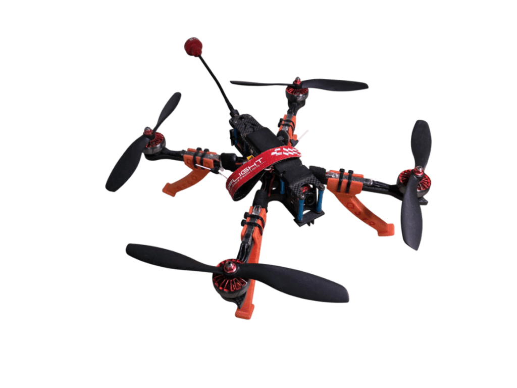
In STEP 1, we selected the frame. Initially, we considered using an existing 7-inch long-range FPV aircraft that we already had on hand.
However, with a 7-inch platform, efficiency, thermal load, and endurance tend to degrade sharply in the 0.7–1.2 kg payload range. In particular, once the payload exceeds 1 kg, there is a high likelihood that flight time drops into the sub-10-minute range, which can leave insufficient operational margin for mission loops such as “drop-off and return.”
In other words, a 7-inch-class aircraft has a clear operational ceiling. If we assume repeated sorties and field operation, the risks increase significantly in terms of overheating, efficiency loss, and return stability.
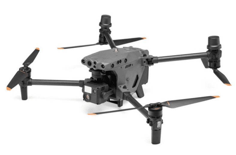
In addition, DJI’s Matrice 30 series (M30/M30T) one of the most widely used commercial platforms for search operations is a ~668 mm-class airframe, and its dedicated propeller (1671) is specified with a disc diameter of approximately 40.6 cm (16 inches). This supports the direction that, to carry payloads and operate stably for extended durations, a large-diameter (≈16-inch) propeller and a correspondingly scaled frame are required.
Component Selection Procedure via Iterative Convergence
To resolve the interdependencies inherent in propulsion sizing, we finalized the specifications through an iterative convergence approach. Because all-up weight (AUW) and the motor/battery specifications are mutually dependent, it is difficult to lock everything in with a single, one-pass calculation. Instead, we converge on the final configuration using the workflow below.
- Fix baseline constraints: Lock the mission requirements, platform scale (15-inch class), and voltage system (6S).
- Pre-fix the propeller: Define diameter/pitch first to constrain the motor candidate range.
- Estimate dry weight: Sum all components excluding the battery to obtain a weight range.
- Estimate battery weight and AUW: Assume a battery weight ratio to converge on an AUW target.
- Initial motor selection: Compute required thrust using hover thrust (AUW/4) and the target TWR (≈ 2.2).
- Bench validation: Verify hover throttle, maximum thrust, and maximum current for candidate motors.
- Spec-up decision: If the target TWR is not met, move to a higher motor class.
- Finalize ESC rating: Apply an operational margin (1.3–1.5×) to the maximum current to determine the ESC rating.
- Converge and finalize the battery: With 6S fixed, narrow down capacity/weight candidates based on target endurance, then make the final selection.
STEP 2 : Finalize the Frame and Propeller
In STEP 2, we fixed the frame and propeller first, prioritizing efficiency. For long-endurance hovering with payload, even at the same thrust level, a larger propeller disc area generally improves hover efficiency which lowers the required current and allows the design to extend overall flight time.
Therefore, to establish the baseline for propulsion sizing, we finalized the frame/propeller configuration as follows:
- Frame: 15-inch propeller-class frame (~650 mm class)
- Propeller: GEMFAN 1540 (15×4) Slow Fly Carbon Fiber
We selected the 15×4 combination for three reasons. First, the 15-inch diameter secures sufficient disc area, improving hover efficiency. Second, the low pitch (4″) reduces aerodynamic load in hover and low-speed regimes, helping to lower current draw and thermal stress. Finally, the “Slow Fly” characteristic aligns well with a mission profile centered on steady-speed flight and hovering rather than high-speed maneuvers—making it advantageous for executing search and return loops with higher stability and margin.


[GEMFAN] 1540 Slow Fly Carbon Fiber
STEP 3 : Dry Weight Estimation and AUW (All-Up Weight) Definition
In STEP 3, to estimate AUW in a reasonable way even while the motor/ESC/battery were still undecided, we first defined the dry weight (aircraft weight excluding the battery) and performed an initial range-based estimate. We then fixed a representative value and applied a battery weight ratio (30–35%) to converge on the aircraft’s total weight, AUW (All-Up Weight).
3-1) Dry Weight Estimation
To define AUW while the battery was still undecided, we first defined the aircraft weight excluding the battery as dry weight (Drone Dry Weight). At this stage, the motor/ESC were also not finalized, so we set a realistic range by summing the components that a 15-inch-class platform would typically require.
- Frame (approx.): 0.81 kg
- 15-inch propellers (×4): 0.08–0.15 kg
- Motors (×4): 0.40–0.80 kg
- ESCs (×4): 0.10–0.28 kg
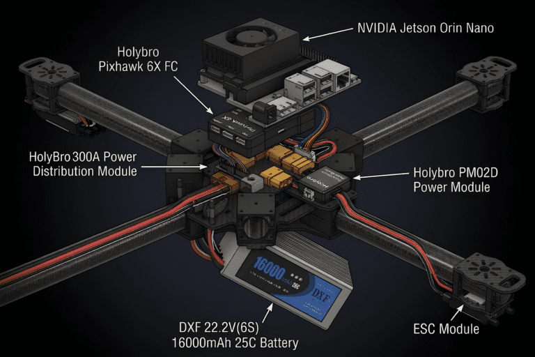
- Avionics & distribution (FC, GPS, receiver, Jetson, PDB, etc.): 0.50 kg
- Wiring/connectors (XT90) & fasteners: 0.10–0.20 kg
- Landing gear/brackets/mounts: 0.15–0.40 kg
- Power electronics (regulator/BEC/sensors, etc.): 0.05–0.15 kg
- Payload (operational assumption): 1.00 kg
By summing these items, the dry-weight range becomes as follows.
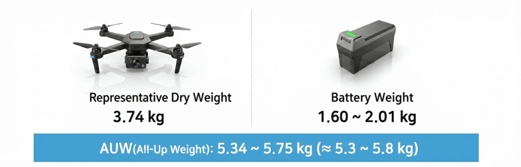
3-2) Representative Dry Weight (Average Value)
For subsequent calculations, we used the average value as the representative dry weight.
Therefore, we fixed the representative dry weight at 3.74 kg.
3-3) Battery Ratio Assumption (30–35%) → Estimating AUW and Battery Weight
Let r be the assumed battery weight ratio (e.g., 30%, so r = 0.30).
Based on the representative dry weight, AUW can be back-calculated as follows.
— Assuming a 30% Battery Weight Ratio (r = 0.30) —
— Assuming a 35% Battery Weight Ratio (r = 0.35) —
Result
- Representative dry weight: 3.74 kg
- Battery weight: 1.60–2.01 kg
- AUW (All-Up Weight): 5.34–5.75 kg (≈ 5.3–5.8 kg)
In the subsequent motor/ESC/battery selection steps, we will use the finalized AUW (5.34–5.75 kg) as the input and converge on the propulsion system design.
STEP 4 : Initial Motor Selection and Datasheet-Based Performance Validation
In STEP 4, we selected the initial motor candidates and calculated the required thrust per motor based on AUW. We then checked the datasheets to confirm whether the hovering operating point fell within an appropriate range.
- →
- →
In other words, during hover, each motor must produce approximately 1.33–1.44 kgf of thrust.
Next, using the MN4010 KV370 datasheet (at 22.2 V with a T-MOTOR 15×5 CF propeller), we matched and checked the hover-throttle operating range.
- 65%: 1300g, 7.0A, 155.4W
- 75%: 1620g, 9.3A, 206.5W
- 100%: 2240g, 14.6A, 324.1W
The required hover thrust falls within the 65–75% throttle range. Around 65%, the requirement is closely matched, enabling efficient hovering. However, as the operating point approaches 75% throttle, the interpretation shifts from “more margin” to less available throttle headroom. In other words, during moments that demand additional thrust—such as wind gusts, aggressive maneuvers, or climb-outs—the usable reserve can shrink, potentially reducing operational margin.

STEP 5 : Initial ESC Selection Based on the MN4010
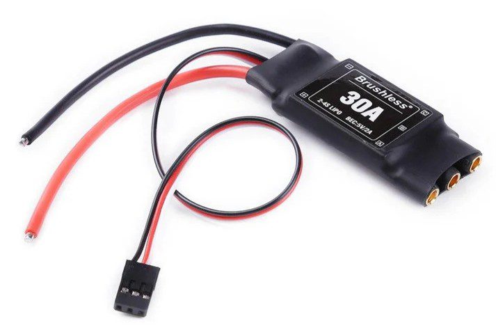
In STEP 5, we selected the initial ESC based on the baseline option (MN4010). From the datasheet, the MN4010 KV370( + 1550 prop) shows a maximum current of 14.6 A. To account for real-world factors such as thermal load and environmental variability, we applied the same operational margin of 1.3–1.5×.
In other words, the calculated required current rating is approximately 19–21.0 A. To comfortably exceed this requirement—and to secure additional margin for thermal headroom and reliability in real-world operation—we set the initial ESC shortlist to the 30 A class.
STEP 6 : TWR Calculation and Thrust Check for the MN4010
In STEP 7, to re-validate whether the target thrust-to-weight ratio (TWR ≈ 2.2) is satisfied, we quantitatively compared the required maximum thrust based on AUW with the maximum thrust of the MN4010 370KV.
First, the maximum thrust required per motor at the target TWR (2.2) is as follows:
- →
- →
In other words, to satisfy the target TWR ≈ 2.2, each motor needs a maximum thrust of approximately 2.94–3.16 kgf.
Next, we compared this requirement against the datasheet maximum thrust of the MN4010 KV370 (with a 15×5 propeller). The datasheet lists a maximum thrust of 2240 g = 2.24 kgf, which leads to the following relationship when compared to the target requirement:
Therefore, under the target TWR ≈ 2.2, the MN4010 does not provide sufficient thrust margin.
To state this explicitly in terms of the actual TWR, based on the MN4010’s maximum thrust of 2.24 kgf per motor, the total maximum thrust becomes:
and, at AUW (5.34–5.75 kg), the actual TWR is: (TWR = Thrust ÷ Weight)
In other words, the MN4010 yields a TWR of approximately 1.56–1.68, which falls short of the target (TWR ≈ 2.2).
In conclusion, while the MN4010 can support hovering, it does not meet the project’s required operational margin (TWR ≈ 2.2). Therefore, a spec-up to a higher motor class was necessary.
STEP 7: Second-Round Motor Selection and Datasheet-Based Performance Validation
In STEP 7, after stepping up to a higher motor class, we calculated the required thrust per motor based on AUW. We then reviewed the datasheets to confirm that the hover operating point falls within an appropriate range.
The required hover thrust per motor at AUW is as follows:
- →
- →
During hover, each motor must produce approximately 1.33–1.44 kgf of thrust.
Next, using the MN5212 KV420 datasheet (at 22.2 V with a T-MOTOR 15×5 CF propeller), we matched and checked the hover-throttle operating range.
- 50%: 1204g
- 55% throttle: 1478 g (≈ close to the hover requirement)
- 65%: 1983g
- 75%: 2589g
- 85% throttle: 3230 g (≈ key point near the target TWR regime)
- 100%: 4175g
The hover thrust requirement is met at approximately 55% throttle. Compared to the initial option (MN4010), this configuration achieves hover at a lower throttle setting, which is advantageous for reducing current draw and thermal load in the real operating regime while securing additional control margin (throttle headroom).

STEP 8: Second-Round ESC Selection Based on the MN5212
In STEP 8, we selected the second-round ESC based on the final motor choice (MN5212). From the datasheet, the MN5212 KV420( + 1550 prop) shows a maximum current of 36.7 A. To account for real-world factors such as thermal load and environmental variability, we applied the same operational margin of 1.3–1.5×.
The required current rating is estimated to be in the ~47.7–55.1 A range. To comfortably exceed this requirement and secure additional thermal headroom under continuous operation, we finalized the ESC selection to the 60 A class.

STEP 9: Verifying Whether the MN5212 Meets the Target Thrust Requirement
In STEP 9, to re-validate whether the target thrust-to-weight ratio (TWR ≈ 2.2) is satisfied, we quantitatively compared the required maximum thrust based on AUW with the maximum thrust of the MN5212 KV420.
First, the maximum thrust required per motor at the target TWR (2.2) is as follows:
To satisfy the target TWR ≈ 2.2, each motor needs a maximum thrust of approximately 2.94–3.16 kgf.
Next, we compared this requirement against the datasheet maximum thrust of the MN5212 KV420 (with a 15×5 propeller). The datasheet lists a maximum thrust of 4175 g = 4.175 kgf, which yields the following relationship when compared to the target requirement:
Therefore, under the TWR ≈ 2.2 target, the MN5212 comfortably exceeds the required maximum thrust and provides sufficient thrust margin.
To state this explicitly in terms of the actual TWR, based on the MN5212’s maximum thrust of 4.175 kgf per motor, the total maximum thrust becomes:
and, at the design-target AUW (5.34–5.75 kg), the actual TWR is:
The MN5212 delivers an actual TWR of approximately 2.90–3.13, which comfortably meets the target (TWR ≈ 2.2).
In conclusion, the MN5212 secures sufficient operational margin not only for hovering but also under the target thrust requirement, making it a suitable choice for the project’s performance margin criterion (TWR ≈ 2.2).
STEP 10: Battery Selection to Meet the Key Performance Indicators (KPIs)
In STEP 10, with the 6S voltage system fixed, we first converged on a set of battery capacity/weight candidates that could meet the 30-minute target endurance. We then finalized the selection based on measured values and the specifications of the purchased battery.
The approach is as follows:
- Estimate the required energy (Wh) to meet the 30-minute target
- Convert energy (Wh) to capacity (Ah)
- Screen and organize candidates to avoid the weight-spiral effect where increased battery mass raises AUW
10-1) 30-Minute Endurance Target, Baseline Battery Capacity Candidates
The energy required for a 30-minute (0.5 h) flight can be approximated as:
Energy (Wh) ≈ Hover power loading (W/kg) × AUW × Time
In addition, we assume we do not use 100% of the battery and apply an effective usable fraction of 80% (0.8).
- Assumed hover power loading: 100–140 W/kg
- Endurance time: 0.5 h (30 minutes)
- Usable fraction: 0.8
Since the design AUW derived in STEP 4 is , we use this as the baseline and converge on the 6S requirement within the following approximate range.
- High efficiency (100–120 W/kg) → 6S 16 Ah to 20 Ah
- Moderate efficiency (120–140 W/kg) → 6S 19 Ah to 22 Ah
Therefore, the baseline capacity candidate range for the 30-minute target was set to 6S 16 Ah–22 Ah.
10-2) Convergence from a Weight Perspective
Increasing battery capacity can extend endurance, but it also increases battery mass—raising AUW and, in turn, increasing hover power. This feedback loop can become a weight spiral. Therefore, we constrained the capacity candidates using a battery weight range as well.
- 6S 16Ah: approximately 1.6~2.0kg
- 6S 22Ah: approximately 2.2~2.8kg
Aggressively increasing capacity can raise AUW and ultimately reduce overall efficiency, this design prioritizes consistency with the battery weight target derived in STEP 4 (approximately 1.60–2.01 kg).
10-3) Battery Finalization Criteria at This Stage
Therefore, at the design stage, we set 6S 16Ah class as the primary candidate because it aligns with the battery weight target (1.60–2.01 kg) derived in STEP 4. If needed, we adopt a strategy to decide whether to step up in capacity based on the measured efficiency (W/kg).
- Capacity candidate range: 6S 16Ah–22Ah (a range capable of meeting the 30-minute target)
- Weight target: aligned with 1.60–2.01 kg (based on STEP 4)
- Strategy: start with 16Ah as the baseline → decide whether to scale up based on measured results
10-4) Final Battery Selection
Based on the criteria above (weight alignment + capacity candidate range), we finalized the battery selection as the following product.
- DXF 22.2V(6S) 16000mAh 25C
- 무게 약 2000g
This battery falls within the 16Ah baseline candidate class and weighs around 2.0 kg, which matches the battery weight target range derived in STEP 4. In addition, its 25C discharge rating and XT90 (anti-spark) connector help reduce risks such as voltage sag, arcing/sparks, and thermal stress during high-current operation. For these reasons, we finalized this product as the battery choice for the current stage.

In this post, we summarized the propulsion component selection process for the 911 FALCON drone. We first locked the mission requirements as clear KPIs, then determined the frame/propeller class as the baseline. From there, we shared the step-by-step convergence flow—establishing AUW and finalizing the motor, ESC, and battery through an iterative refinement (iteration) process.
In the next post, we’ll cover the power subsystem (battery, PDB, and power module). We’ll explain how we structured the power architecture to reliably deliver the thrust demanded by the propulsion system, and how we stabilized threshold operations using voltage/current monitoring.
In the following post, we’ll focus on the communications and control subsystem (FC, GPS, receiver, Jetson, and link configuration) and share how we connected flight control and data flow into a cohesive system architecture.
Thank you.

Author: Guenchan lee, Senior Researcher of QUAD Drone Lab.
Date: February 25, 2026
![PX4 MAVSDK – C++ Programming [Part 2] Core C++ Syntax for MAVSDK](https://quad-drone-lab.co.kr/wp-content/uploads/2026/03/0312_인포그래픽-768x768.jpg)
![PX4 MAVSDK – C++ Programming [Episode 10] Custom Logging and Integration Testing (gtest)](https://quad-drone-lab.co.kr/wp-content/uploads/2026/03/0320_인포그래피-768x419.jpg)
![[PX4 Tuning Series Appendix] Racing Drone Tuning Guide (Racer Setup): Unlocking Extreme Performance](https://quad-drone-lab.co.kr/wp-content/uploads/2026/03/Racing-Drone-Minimalism-and-Balance-768x429.png)
![[PX4 Tuning Series 6] Trajectory Generator and Setpoint Tuning: The Art of Flight Feel and Smooth S-Curves](https://quad-drone-lab.co.kr/wp-content/uploads/2026/03/Drone-Trajectory-Comparison-768x429.png)