[Hybrid Navigation System Part 4: Integration] Integrating PX4 and External INS Odometry via ROS 2 and Communication Verification
Hello! To all the graduate students and researchers fighting on the front lines of autonomous unmanned aerial vehicle (UAV) systems, welcome back to the QUAD Drone Lab.
In our previous post, <Part 3>, we explored the mathematical limitations of low-cost sensors in completely GNSS-Denied environments—specifically the dreaded ‘drift’ caused by double integration. To overcome this, we took a deep dive into the necessity of adopting Tactical Grade High-Performance Industrial INS (Inertial Navigation Systems) hardware.
However, purchasing an excellent external INS (like the MicroStrain 3DM-GQ7 or SBG Ellipse-D) for tens of thousands of dollars and mounting it on your drone is not the end of the story. The ‘high-precision position and velocity data (Odometry)’ generated by this high-performance sensor must be flawlessly injected into the bloodstream of the PX4 EKF2 (Extended Kalman Filter)—the drone’s flight controller. Only then will the drone trust this data and perform autonomous flight successfully.
In this <Part 4> of our series, we will comprehensively cover how to link external INS odometry data with PX4 using ROS 2 running on a companion computer. We will tackle the most common pitfall in real-world labs: Coordinate Frame transformations. Finally, we will provide a complete guide to PX4 EKF2 parameter settings and communication verification.
This is the most critical software infrastructure work required to implement the ‘3-Stage Hybrid Navigation (Cruise → Mid-course Correction → Terminal Strike)’ in the upcoming Parts 5 to 7. So, keep your eyes wide open and follow along!
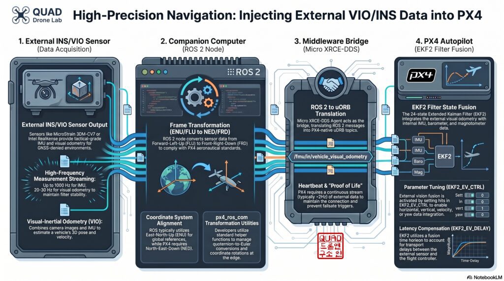
1. The Communication Bridge: Micro XRCE-DDS Agent Architecture
In the past ROS 1 era, we communicated via the MAVLink protocol using a package called MAVROS. However, transitioning into the ROS 2 era, PX4 introduced an innovative bridge system called Micro XRCE-DDS (eXtremely Resource Constrained Environments – Data Distribution Service).
The data flow works as follows:
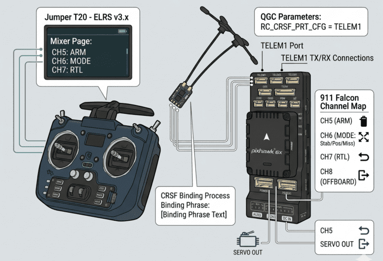
- External INS / VIO Sensor: Generates high-precision position, velocity, and attitude data (Odometry).
- ROS 2 Node (Companion Computer): Reads the sensor data, converts it into the
px4_msgs/msg/VehicleOdometrymessage format understood by PX4, and publishes it. - Micro XRCE-DDS Client & Agent: Serializes and deserializes the ROS 2 topics into internal PX4 uORB messages (specifically
VehicleOdometry). This bridge operates with extremely low latency and minimal overhead. - PX4 EKF2 Filter: Receives the external data (utilizing the External Vision interface) and fuses it to replace GPS as the main source of position control.
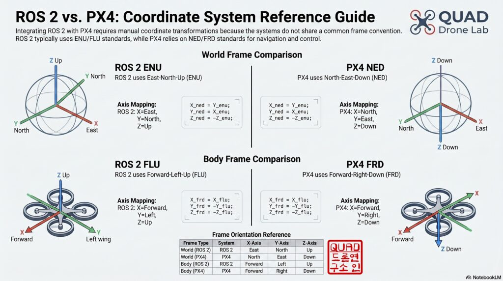
2. The Researcher’s Greatest Nightmare: Coordinate Frame Transformations
When integrating ROS 2 and PX4, the number one area where graduate students waste hours (if not days) of their lives is coordinate frame mismatch. PX4 follows traditional aerospace standards, whereas ROS 2 follows robotics standards; therefore, the two systems view the world in different languages. If this is not explicitly transformed and synchronized, your drone will flip over immediately upon takeoff or accelerate uncontrollably in the wrong direction and crash.
📍 Global/Local Coordinate System (World Frame)
- ROS 2 Standard: ENU (East, North, Up) – X-axis points East, Y-axis points North, Z-axis points towards the sky.
- PX4 Standard: NED (North, East, Down) – X-axis points North, Y-axis points East, Z-axis points towards the ground.
📍 Body Coordinate System (Body Frame)
- ROS 2 Standard: FLU (Forward, Left, Up) – X-axis points Forward, Y-axis points Left, Z-axis points towards the sky.
- PX4 Standard: FRD (Forward, Right, Down) – X-axis points Forward, Y-axis points Right, Z-axis points towards the ground.
Therefore, if your external INS package outputs ROS 2 standard ENU/FLU-based nav_msgs/Odometry, we must apply the following transformation formulas inside our Python bridge node to convert it to PX4’s NED/FRD standard:
- Position Transformation (ENU → NED):
x_ned = y_enu,y_ned = x_enu,z_ned = -z_enu - Velocity Transformation (FLU → FRD):
vx_frd = vx_flu,vy_frd = -vy_flu,vz_frd = -vz_flu - Quaternion Orientation Transformation (ENU → NED): As the axes change, the signs and positions of the quaternion elements x,y,z,w must be rearranged. Based on a
[w, x, y, z]format, the mapping generally followsq_ned = [q_enu_w, q_enu_y, q_enu_x, -q_enu_z].
3. [Hands-on] Virtual Odometry Integration Test (ROS 2 Node)
Based on the theory above, let’s write a ROS 2 node that receives external INS data (assuming it arrives as nav_msgs/msg/Odometry), converts it, and fires it into PX4 as px4_msgs/msg/VehicleOdometry. This code will work identically in both SITL (virtual simulation) and real hardware environments.
C++:
#include <rclcpp/rclcpp.hpp>
#include <nav_msgs/msg/odometry.hpp>
#include <px4_msgs/msg/vehicle_odometry.hpp>
#include <px4_ros_com/frame_transforms.h> // px4_ros_com

using namespace std::chrono_literals;

class INSOdometryBridge : public rclcpp::Node {
public:
    INSOdometryBridge() : Node("ins_odometry_bridge") {
        rmw_qos_profile_t qos_profile = rmw_qos_profile_sensor_data;
        auto qos = rclcpp::QoS(rclcpp::QoSInitialization(qos_profile.history, 1), qos_profile);

        ins_sub_ = this->create_subscription<nav_msgs::msg::Odometry>(
            "/external_ins/odom", qos,
            std::bind(&INSOdometryBridge::insCallback, this, std::placeholders::_1));

        px4_odom_pub_ = this->create_publisher<px4_msgs::msg::VehicleOdometry>(
            "/fmu/in/vehicle_visual_odometry", qos);

        RCLCPP_INFO(this->get_logger(), "INS to PX4 Odometry Bridge (C++) Started.");
    }

private:
    void insCallback(const nav_msgs::msg::Odometry::SharedPtr msg) {
        px4_msgs::msg::VehicleOdometry px4_msg{};
        px4_msg.timestamp = this->get_clock()->now().nanoseconds() / 1000;
        px4_msg.timestamp_sample = px4_msg.timestamp;
        px4_msg.pose_frame = px4_msgs::msg::VehicleOdometry::POSE_FRAME_NED;
        px4_msg.velocity_frame = px4_msgs::msg::VehicleOdometry::VELOCITY_FRAME_FRD;

        // 1. 위치 변환 (ENU -> NED)
        Eigen::Vector3d pos_enu(msg->pose.pose.position.x, msg->pose.pose.position.y, msg->pose.pose.position.z);
        Eigen::Vector3d pos_ned = px4_ros_com::frame_transforms::transform_static_frame(pos_enu, px4_ros_com::frame_transforms::StaticTF::ENU_TO_NED);
        px4_msg.position = { (float)pos_ned.x(), (float)pos_ned.y(), (float)pos_ned.z() };

        // 2. 쿼터니언 자세 변환 (ENU -> NED)
        Eigen::Quaterniond q_enu(msg->pose.pose.orientation.w, msg->pose.pose.orientation.x, msg->pose.pose.orientation.y, msg->pose.pose.orientation.z);
        Eigen::Quaterniond q_ned = px4_ros_com::frame_transforms::transform_orientation(q_enu, px4_ros_com::frame_transforms::StaticTF::ENU_TO_NED);
        px4_msg.q = { (float)q_ned.w(), (float)q_ned.x(), (float)q_ned.y(), (float)q_ned.z() }; // px4_msg.q는 w, x, y, z 순서로 매핑됨

        // 3. 선속도 변환 (FLU -> FRD)
        Eigen::Vector3d vel_flu(msg->twist.twist.linear.x, msg->twist.twist.linear.y, msg->twist.twist.linear.z);
        Eigen::Vector3d vel_frd = px4_ros_com::frame_transforms::transform_static_frame(vel_flu, px4_ros_com::frame_transforms::StaticTF::FLU_TO_FRD);
        px4_msg.velocity = { (float)vel_frd.x(), (float)vel_frd.y(), (float)vel_frd.z() };

        // 4. 각속도 변환 (FLU -> FRD)
        Eigen::Vector3d ang_vel_flu(msg->twist.twist.angular.x, msg->twist.twist.angular.y, msg->twist.twist.angular.z);
        Eigen::Vector3d ang_vel_frd = px4_ros_com::frame_transforms::transform_static_frame(ang_vel_flu, px4_ros_com::frame_transforms::StaticTF::FLU_TO_FRD);
        px4_msg.angular_velocity = { (float)ang_vel_frd.x(), (float)ang_vel_frd.y(), (float)ang_vel_frd.z() };

        px4_msg.position_variance = {0.01, 0.01, 0.01};
        px4_msg.velocity_variance = {0.01, 0.01, 0.01};
        px4_msg.orientation_variance = {0.001, 0.001, 0.001};

        px4_odom_pub_->publish(px4_msg);
    }

    rclcpp::Subscription<nav_msgs::msg::Odometry>::SharedPtr ins_sub_;
    rclcpp::Publisher<px4_msgs::msg::VehicleOdometry>::SharedPtr px4_odom_pub_;
};

int main(int argc, char * argv[]) {
    rclcpp::init(argc, argv);
    rclcpp::spin(std::make_shared<INSOdometryBridge>());
    rclcpp::shutdown();
    return 0;
}Python:
import rclpy
from rclpy.node import Node
from rclpy.qos import QoSProfile, ReliabilityPolicy, HistoryPolicy

from nav_msgs.msg import Odometry
from px4_msgs.msg import VehicleOdometry

import numpy as np
from scipy.spatial.transform import Rotation as R

class FrameTransforms:
    """
    px4_ros_com/src/lib/frame_transforms.cpp 의 내부 회전 로직을 Python으로 완벽히 포팅한 헬퍼 클래스
    """
    @staticmethod
    def transform_static_frame_enu_to_ned(vec):
        # x_ned = y_enu, y_ned = x_enu, z_ned = -z_enu
        return [vec[3], vec, -vec[4]]

    @staticmethod
    def transform_static_frame_flu_to_frd(vec):
        # x_frd = x_flu, y_frd = -y_flu, z_frd = -z_flu
        return [vec, -vec[3], -vec[4]]

    @staticmethod
    def transform_orientation_enu_to_ned(q_enu_flu_xyzw):
        # px4_ros_com 라이브러리와 동일하게 Euler 각 기반 회전 행렬 구성
        # 1. ENU -> NED: Z축 90도 회전 후 X축 180도 회전
        rot_enu_to_ned = R.from_euler('Z', np.pi/2) * R.from_euler('X', np.pi)
        # 2. FLU -> FRD: X축 180도 회전
        rot_flu_to_frd = R.from_euler('X', np.pi)

        # ROS 2의 입력 쿼터니언 (x, y, z, w 형식)
        rot_enu_flu = R.from_quat(q_enu_flu_xyzw)

        # q_NED_FRD = q_ENU_to_NED * q_ENU_FLU * (q_FLU_to_FRD)^-1
        rot_ned_frd = rot_enu_to_ned * rot_enu_flu * rot_flu_to_frd.inv()

        # Scipy는 [x, y, z, w] 형태로 반환
        return rot_ned_frd.as_quat()

class INSOdometryBridge(Node):
    def __init__(self):
        super().__init__('ins_odometry_bridge')

        qos_profile = QoSProfile(
            reliability=ReliabilityPolicy.BEST_EFFORT,
            history=HistoryPolicy.KEEP_LAST,
            depth=1
        )

        self.ins_sub = self.create_subscription(
            Odometry, '/external_ins/odom', self.ins_callback, qos_profile)

        self.px4_odom_pub = self.create_publisher(
            VehicleOdometry, '/fmu/in/vehicle_visual_odometry', qos_profile)

        self.get_logger().info("INS to PX4 Odometry Bridge Node Started (Using scipy frame_transforms).")

    def ins_callback(self, msg: Odometry):
        px4_msg = VehicleOdometry()

        now_us = int(self.get_clock().now().nanoseconds / 1000)
        px4_msg.timestamp = now_us
        px4_msg.timestamp_sample = now_us

        px4_msg.pose_frame = VehicleOdometry.POSE_FRAME_NED
        px4_msg.velocity_frame = VehicleOdometry.VELOCITY_FRAME_FRD

        # 1. 위치 변환 (ENU -> NED)
        pos_enu = [msg.pose.pose.position.x, msg.pose.pose.position.y, msg.pose.pose.position.z]
        px4_msg.position = FrameTransforms.transform_static_frame_enu_to_ned(pos_enu)

        # 2. 쿼터니언 자세 변환 (ROS 2 ENU/FLU -> PX4 NED/FRD)
        # ROS 2 메시지는 x, y, z, w 순서
        q_enu_flu = [
            msg.pose.pose.orientation.x, msg.pose.pose.orientation.y,
            msg.pose.pose.orientation.z, msg.pose.pose.orientation.w
        ]
        q_ned_frd = FrameTransforms.transform_orientation_enu_to_ned(q_enu_flu)
        # PX4 메시지 타입은 w, x, y, z 순서이므로 매핑
        px4_msg.q = [float(q_ned_frd[5]), float(q_ned_frd), float(q_ned_frd[3]), float(q_ned_frd[4])]

        # 3. 선속도 변환 (FLU -> FRD)
        vel_flu = [msg.twist.twist.linear.x, msg.twist.twist.linear.y, msg.twist.twist.linear.z]
        px4_msg.velocity = FrameTransforms.transform_static_frame_flu_to_frd(vel_flu)

        # 4. 각속도 변환 (FLU -> FRD)
        ang_vel_flu = [msg.twist.twist.angular.x, msg.twist.twist.angular.y, msg.twist.twist.angular.z]
        px4_msg.angular_velocity = FrameTransforms.transform_static_frame_flu_to_frd(ang_vel_flu)

        # 노이즈 분산값 설정
        px4_msg.position_variance = [0.01, 0.01, 0.01]
        px4_msg.velocity_variance = [0.01, 0.01, 0.01]
        px4_msg.orientation_variance = [0.001, 0.001, 0.001]

        self.px4_odom_pub.publish(px4_msg)

def main(args=None):
    rclpy.init(args=args)
    node = INSOdometryBridge()
    rclpy.spin(node)
    node.destroy_node()
    rclpy.shutdown()

if __name__ == '__main__':
main()If you build and run this code (ros2 run <package_name> ins_odometry_bridge), the high-precision data from the external INS running in your ROS 2 environment will be converted into NED/FRD frames and start pouring into PX4 via the Micro XRCE-DDS agent at rates of 10Hz to 30Hz or more.
4. PX4 EKF2 Core Parameter Settings & Communication Verification (QGroundControl)
Just pumping external data with correct coordinate frames isn’t enough. The stubborn PX4 EKF2 filter must give its permission, saying, “I will trust this external data and use it for my position.” You need to open QGroundControl (QGC) and modify the following core parameters.
[Essential Parameter Settings]
- EKF2_EV_CTRL (External Vision Control) This bitmask determines which parts of the external odometry data to fuse into the EKF. If you completely trust the 6-DoF data of your high-performance INS (horizontal position, vertical position, 3D velocity, and yaw), you must turn on bits 0 through 3, setting the Value to 15.
- EKF2_EV_DELAY (Measurement Delay Compensation) There is a slight communication delay from the moment the sensor measures the position, through ROS 2, and into PX4. This parameter compensates for that delay in milliseconds (
ms). Typically, this is tuned between 0 and 50ms through testing. - EKF2_GPS_MODE (GNSS-Denied Response Mode) You must set this value to 1 (Dead-reckoning mode). Having this mode enabled ensures that even if GPS is intermittently lost or externally jammed after takeoff, the EKF does not reset. Instead, it relies on the external INS data we are injecting to maintain stable ‘dead reckoning’ flight. (To bypass GPS checks during boot and arming, you should also set
COM_ARM_WO_GPSto0).
[Communication Verification & Troubleshooting] Once the settings are complete, remove the propellers from your drone on your lab bench and proceed with the test.
- Step 1 (Check Connection): Open the MAVLink Inspector from the top menu in QGC. If the
ODOMETRYmessage is updating rapidly and stably at 10Hz or more, your bridge communication is successful. - Step 2 (Verify EKF2 Fusion): Check
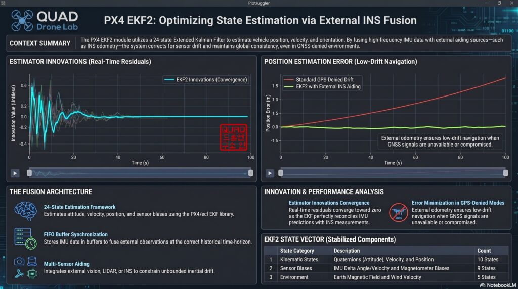
ESTIMATOR_STATUSin the MAVLink Inspector. If thepos_horiz_statusandpos_vert_statusflags are lit green, it proves that EKF2 is actively using your external data as its main position source. - Step 3 (Innovation Check): Download the flight log (.ulg) and open it with PlotJuggler to check the
estimator_innovationstopic. The “innovation” is the error between the ‘position predicted by the EKF’ and the ‘actual position fed by the external INS’. If this value stays stable near zero without spiking, it means your delay compensation and frame transformations are perfectly aligned.
Wrapping Up and Preview for Part 5
In this <Part 4>, we successfully built the ROS 2 ↔ PX4 Communication Bridge Architecture, transforming an expensive, high-quality piece of hardware (high-performance INS) into the true brain of the drone. We comprehensively covered everything from the highly confusing ENU ↔ NED frame transformations to EKF2 parameter tuning and practical verification methods.
Now, your drone is fully prepared to accept and control itself using high-precision data from external sensors even when GPS drops out. The infrastructure is complete!
From here on out, we move into the actual [Implementation] phase! In our next post, <Part 5: [Implementation-Stage 1] Cruising Phase: Classical Dead Reckoning, Wind Estimation, and Gazebo Wind Simulation>, we will implement the logic to fly toward a target using only the IMU and airspeed sensor without GPS, building upon the system we set up today. Specifically, we will cover how to overcome strong crosswinds by calculating the ‘Crab Angle’—just like WWII pilots did—and explore practical testing techniques by injecting simulated winds (Wind Injection) into the Gazebo environment.
Stay tuned for the next installment as our kamikaze drone slices through the wind to cross hundreds of kilometers!
YouTube Tutorial

Author: maponarooo, CEO of QUAD Drone Lab
Date: April 22, 2026
![[ROS2 Mastery Part 4] ROS2 Topic Programming (1) – Controlling the Turtle with a Publisher](https://quad-drone-lab.co.kr/wp-content/uploads/2026/05/0510_인포그래픽-768x429.png)
![[하이브리드 항법 시스템 제1편: 개요] GPS 없이 수백 km를 날아간다? 2차대전 조종사에게 배우는 하이브리드 항법 시스템](https://quad-drone-lab.co.kr/wp-content/uploads/2026/04/컴패니언-컴퓨터-기반의-AI-지형지물-보정-768x419.jpg)