[Hybrid Navigation System: Part 6] [Implementation-Phase 2] Intermediate Correction: OpenCV/YOLO Terrain Matching and Digital Twin Testing
Hello! To all the graduate students and researchers burning the midnight oil at the forefront of autonomous unmanned aerial vehicle (UAV) systems—welcome back to the QUAD Drone Lab.
In Part 5, we explored PX4’s Dead-Reckoning mode, a critical software safety net that allows a drone to survive and maintain flight in GNSS-Denied environments, such as deep urban canyons or areas under severe enemy GPS jamming. While dead-reckoning utilizing an Inertial Measurement Unit (IMU) and Visual Odometry (VIO) guarantees highly stable flight over short durations, we fundamentally cannot avoid the drift phenomenon, where sensor errors accumulate over time causing the position estimate to gradually diverge.
For long-range reconnaissance UAVs or kamikaze drones that must fly hundreds of kilometers to precisely strike a target, an ‘Intermediate Correction’ phase is absolutely essential to reset these accumulated errors mid-flight.
Today, in Part 6, we will modernize the concept of TERCOM (Terrain Contour Matching)—historically used in cruise missiles—and dive deep into Absolute Visual Localization (AVL) technology using OpenCV and YOLO deep learning models. We will also cover how to safely validate this complex system using a Digital Twin simulation environment!
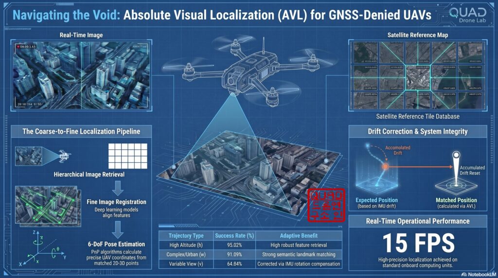
1. Absolute Visual Localization (AVL) and the Evolution of Terrain Matching
Back in the 1970s, cruise missiles utilized TERCOM (Terrain Contour Matching), a system that measured terrain elevation using a radar altimeter and compared it against an onboard Digital Elevation Model (DEM). However, in modern UAV operations, active radars risk exposing the drone’s position to enemy detection. Thus, the trend has shifted toward passive camera (Vision)-based navigation, which consumes less power and emits no radio waves.
The technology that calculates the aircraft’s exact latitude and longitude by directly comparing downward-facing real-time camera imagery with pre-loaded, geo-tagged reference maps (like satellite or aerial orthophotos) is called Absolute Visual Localization (AVL). AVL fundamentally eliminates the cumulative drift inherent in Relative Visual Localization (RVL) like VIO, acting as a powerful tool that provides independent absolute coordinates for every frame.
2. Two Core Technologies for Intermediate Correction: OpenCV vs. YOLO
Methods for calculating position errors by matching terrain features can be broadly divided into traditional image processing techniques and modern deep learning-based approaches. Researchers must choose or fuse these technologies based on the mission environment and available computing resources.
📍 Approach A: OpenCV Template Matching
Template matching is a classical and intuitive method that slides the UAV’s real-time image (Template) over the entire reference satellite map (Source) to find the most similar region.
- Pros: Very simple to implement and requires minimal computing resources. It can be applied immediately without any complex training process.
- Mechanism: It utilizes OpenCV’s
cv2.matchTemplate()function, typically adopting the Normalized Cross-Correlation (TM_CCOEFF_NORMED) method, which is somewhat robust to slight lighting changes and noise. - Limitations: It is highly vulnerable to scale changes caused by UAV altitude variations or view angle changes caused by aircraft rotation. Therefore, it is best suited for fixed-wing aircraft checking specific ‘waypoints’ while maintaining a constant altitude and heading.
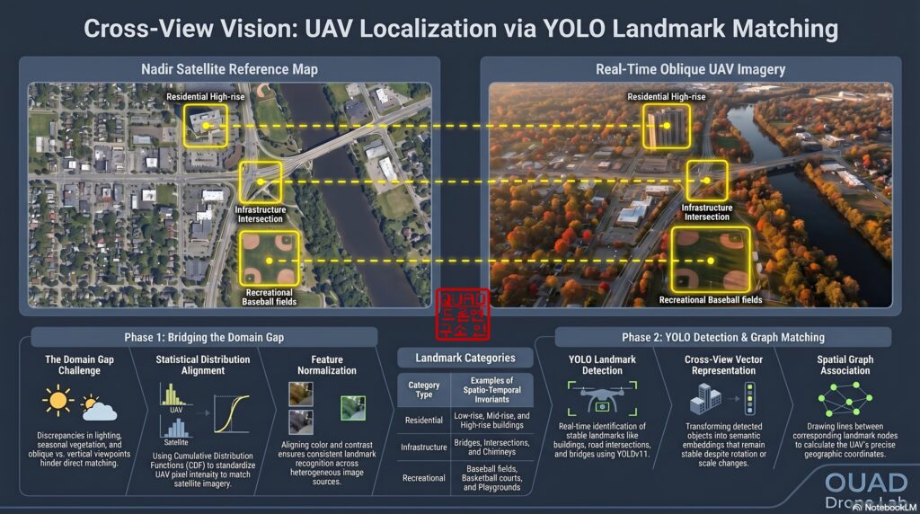
📍 Approach B: YOLO-Based Terrain Landmark Detection
Pre-loaded satellite images might be years old or reflect a specific season, whereas real-time UAV video reacts sensitively to shadows, weather, and vegetation changes. This creates a massive ‘Domain Gap’ between the two views. To overcome this cross-view limitation, the YOLO (You Only Look Once) object detection algorithm is introduced.
- Characteristics: Models ranging from YOLOv8 and YOLO11 to the latest YOLO26 are highly optimized to run in real-time on edge devices (like the NVIDIA Jetson series).
- Mechanism: Instead of matching forests or rivers that change with seasons, the model is trained to detect 16 categories of geometrically invariant landmarks (e.g., low/mid/high-rise buildings, intersections, bridges, stadiums).
- Pros: Extremely robust to scale and rotation changes. By performing Graph Matching or PnP algorithms based on the relative topological layout of multiple detected landmarks, it can estimate a highly accurate 6-DoF (Degrees of Freedom) pose even if the appearance of individual objects has deformed.
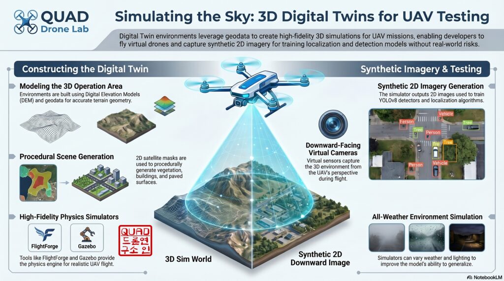
3. Simulation-Based Development via Digital Twins (SITL)
Directly testing such complex AVL systems in real flight carries a massive risk of crashing. In robotics development, it is mandatory to construct a Digital Twin environment that closely mimics the actual target operation area for preliminary verification.
We can generate a 3D environment of the target region using simulators like Gazebo or FlightForge:
- Terrain Generation: Use open-source Digital Elevation Models (DEM) to create terrain with real-world altitudes and contours.
- Texture Mapping & Object Placement: Apply satellite image textures and procedurally generate LoD2 (Level of Detail 2) building models to populate the map.
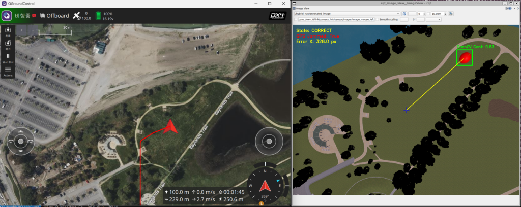
- Verification: Fly a virtual UAV within this 3D digital twin to acquire Synthetic Data via a downward camera sensor plugin. Using this data, we verify if our OpenCV template matching or YOLO models function correctly, and whether the calculated error vectors are accurately fed into PX4 as position correction commands.
4. [Python Practical Example] Intermediate Position Error Calculator
Below is a Python example code designed to run on an onboard companion computer (e.g., Jetson Orin) in a ROS 2 environment. This script takes the real-time UAV feed and a pre-loaded satellite map (checkpoint) as inputs, demonstrating the principle of calculating the current pixel error by fusing OpenCV template matching with YOLO object detection.
import cv2
import numpy as np
from ultralytics import YOLO

class HybridVisualLocalizer:
    def __init__(self, satellite_map_path, yolo_model_path):
        """
        Initialization: Load the satellite reference map and the YOLO landmark detection model.
        """
        # Load satellite map (Grayscale conversion improves template matching efficiency)
        self.satellite_map_color = cv2.imread(satellite_map_path)
        self.satellite_map_gray = cv2.cvtColor(self.satellite_map_color, cv2.COLOR_BGR2GRAY)

        # Load pre-trained YOLO model for detecting landmarks (buildings, intersections, etc.)
        print("Loading YOLO model for landmark detection...")
        self.yolo_model = YOLO(yolo_model_path)

    def match_by_template(self, uav_frame):
        """
        Approach A: Calculate position error using classical OpenCV Template Matching.
        """
        uav_gray = cv2.cvtColor(uav_frame, cv2.COLOR_BGR2GRAY)
        h, w = uav_gray.shape

        # Search for the UAV image's position within the satellite map using Normalized Cross-Correlation
        result = cv2.matchTemplate(self.satellite_map_gray, uav_gray, cv2.TM_CCOEFF_NORMED)
        min_val, max_val, min_loc, max_loc = cv2.minMaxLoc(result)

        # Consider it a successful match only if the confidence (max_val) exceeds the threshold
        if max_val > 0.65:
            top_left = max_loc
            center_x = top_left + w // 2
            center_y = top_left[1] + h // 2
            print(f"[Template Match] Success! Center coords: ({center_x}, {center_y}), Confidence: {max_val:.2f}")
            return (center_x, center_y), max_val
        else:
            print("[Template Match] Failed due to low confidence.")
            return None, max_val

    def detect_landmarks(self, image):
        """
        Approach B: Extract terrain landmark features (buildings, etc.) utilizing YOLO.
        """
        # Detect landmark objects within the image
        results = self.yolo_model(image, conf=0.5, verbose=False)
        landmarks = []
        for box in results.boxes:
            # Calculate the center coordinates of the Bounding Box
            x_center = float(box.xywh)
            y_center = float(box.xywh[1])
            class_id = int(box.cls)
            landmarks.append({"x": x_center, "y": y_center, "cls": class_id})
        return landmarks

    def calculate_position_error(self, uav_frame, expected_map_x, expected_map_y):
        """
        Hybrid Processing: Find the position via template matching, then
        verify with YOLO landmark nodes to calculate and return the final Error Vector.
        """
        # 1. Primary position estimation via Template Matching
        matched_loc, conf = self.match_by_template(uav_frame)

        if matched_loc:
            matched_x, matched_y = matched_loc

            # 2. Identify objects within the view via YOLO landmark detection (for semantic/geometric verification)
            uav_landmarks = self.detect_landmarks(uav_frame)
            print(f"[YOLO] Found {len(uav_landmarks)} landmarks in the UAV frame.")

            # (In a real environment, Graph Matching networks or PnP algorithms would be applied here
            #  to convert 2D landmark pairs into 3D absolute coordinates.)

            # 3. Calculate Error Vector: (Expected Coordinates - Actual Matched Coordinates)
            # By multiplying this pixel error by the spatial resolution (GSD, m/pixel),
            # we derive the physical deviation in meters (m) to send to the PX4 EKF as a LocalPositionMeasurement.
            error_x = expected_map_x - matched_x
            error_y = expected_map_y - matched_y

            return error_x, error_y
        return None, None

# Test Execution (Assuming arbitrary image paths)
if __name__ == "__main__":
    localizer = HybridVisualLocalizer("data/satellite_reference.tif", "models/yolov8_landmarks.pt")
    uav_live_frame = cv2.imread("data/uav_camera_current.jpg")

    # The expected pixel coordinates on the satellite map predicted by the drone's INS
    expected_x, expected_y = 1500, 2000

    err_x, err_y = localizer.calculate_position_error(uav_live_frame, expected_x, expected_y)
    if err_x is not None:
        print(f"🚀 [Final Correction Command] X-axis Error: {err_x}px, Y-axis Error: {err_y}px")
        # The drone's flight path will be corrected based on these error values
[Code Explanation]
match_by_template: Slides the real-time drone imagery (uav_frame) over the satellite map to find the point of highest similarity usingcv2.TM_CCOEFF_NORMED.detect_landmarks: In case template matching fails due to seasonal or lighting changes, YOLO is used to detect structurally invariant landmarks (like buildings).calculate_position_error: Computes the deviation (Error) between the estimated coordinates the aircraft predicted (expected) and the actual coordinates matched through vision (matched). Multiplying this pixel error by the camera’s GSD (Ground Sample Distance) yields the physical error in meters, which is then sent to PX4 via the ROS 2 bridge to correct the trajectory.

5. Gazebo Simulation Test
This is a step-by-step guide to testing the entire simulation environment and the visual correction algorithm. You will need to open 4 separate terminals and execute the commands in the sequential order provided below.
“Join our QUAD Drone Lab YouTube channel as a [💎Diamond Member] to get full access to all the textbooks and source code for your flight tests.”
Step 1. Run Micro-XRCE-DDS-Agent (Terminal 1)
Launch the agent that acts as a bridge, enabling uORB messages from PX4 Autopilot to communicate with ROS 2.
MicroXRCEAgent udp4 -p 8888
Step 2. Launch PX4 SITL and Gazebo Simulator (Terminal 2)
Launch the baylands world featuring a drone model equipped with a downward-facing camera and a VIO sensor (x500_vio_cam_down), along with a red apple landmark designed for visual correction.
cd ~/PX4-Autopilot-1.17.0-HybridNav
make px4_sitl gz_x500_vio_cam_down_baylands
Note: Since this node subscribes to an image topic based on the specific world name (/world/baylands/...), you must append _baylands to ensure the correct world is loaded.
Step 3. Launch Gazebo ➡️ ROS 2 Camera Image Bridge (Terminal 3)
Convert (Bridge) the downward-facing camera image data from the Gazebo simulation into a format that can be read by ROS 2 nodes.
ros2 run ros_gz_bridge parameter_bridge /world/baylands/model/x500_vio_cam_down_0/link/camera_link/sensor/imager/image@sensor_msgs/msg/Image[gz.msgs.Image
Step 4. Build and Run the Visual Correction ROS 2 Node (Terminal 4)
Build your ROS 2 workspace and run the control and visual matching node.
cd ~/ros2_ws
colcon build --symlink-install
source install/setup.bash

# Run using the OpenCV Template Matching method (Approach A)
ros2 run hybrid_nav visual_correction_node --ros-args -p approach:=A
(If you wish to test using the YOLO-based object detection method (Approach B), replace the option with -p approach:=B. Note that an internet connection is required to automatically download the necessary deep learning weight file, yolov8n.pt.)
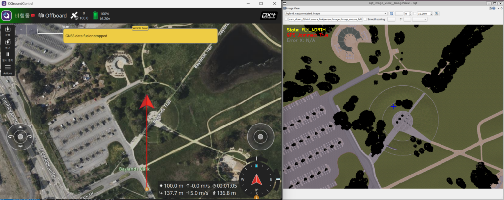
Step 5. Monitor Downward Camera and Visual Matching Status
ros2 run rqt_image_view rqt_image_view
💡 Node Operation Flow & Key Checkpoints
Once the node is running, the flight state machine will automatically execute in the following sequence:
- TAKEOFF: The drone ascends to an altitude of 100 meters.
- FLY_NORTH: Upon reaching 100 meters, the drone begins flying North at a speed of 8 m/s.
- GPS Jamming (Automatic): Exactly 7.5 seconds after the flight begins, the node automatically injects a GPS dropout via MAVLink (
SIM_GPS_USED=0). At this point, the drone transitions into Dead-reckoning mode, maintaining its flight path by relying solely on the VIO sensor.
Wrapping Up
In Part 6, we took a deep dive into ‘Intermediate Visual Correction (Visual Checkpoint)’ technology, which fuses OpenCV and YOLO to calculate absolute vision-based coordinates, ensuring the drone never loses its way even deep in enemy territory or dense urban areas without communications.
True autonomy—free from GNSS reliance—is achieved not just by rudimentary flight control, but when the aircraft can open its own eyes, perceive the world, and literally read a map. We hope rigorous simulations in a Digital Twin environment will perfectly validate your algorithms.
In our next post, Part 7, we will cover the grand finale of hybrid navigation and the most critical final hurdle for kamikaze drones: visually locking onto a target and guiding the drone in for an ultra-precision strike through ‘Terminal Phase: Visual Servoing’.
If you have any questions regarding algorithm design or digital twin integration, please leave a comment at any time. Thank you!
YouTube Tutorial

Author: maponarooo, CEO of QUAD Drone Lab
Date: Jun 09, 2026
![PX4 MAVSDK – C++ Programming [6편] Action API를 이용한 기본 비행 제어](https://quad-drone-lab.co.kr/wp-content/uploads/2026/03/0316_인포그래피-768x512.png)
![[PX4 튜닝 시리즈 7] 착륙 감지기 설정 (Land Detector Configuration): 완벽한 비행의 마무리를 위한 필수 가이드](https://quad-drone-lab.co.kr/wp-content/uploads/2026/03/Drone-Ground-Contact-Landing-Logic-768x429.png)
![[ROS2 Mastery 9편] 싱글 프레임 및 움직이는 로봇 TF2 브로드캐스팅 실습 가이드](https://quad-drone-lab.co.kr/wp-content/uploads/2026/06/0605_인포그래픽-768x429.jpg)
![[ROS2 Mastery 3편] 첫 ROS2 패키지 생성 및 Python 노드(Node) 프로그래밍 가이드](https://quad-drone-lab.co.kr/wp-content/uploads/2026/05/0507_인포그래픽-768x512.png)