
Battery Housing Design : 911 FALCON Project
Hello, this is QUAD Drone Laboratory.
I’m Geunchan Lee, Senior Researcher at QUAD Drone Lab.
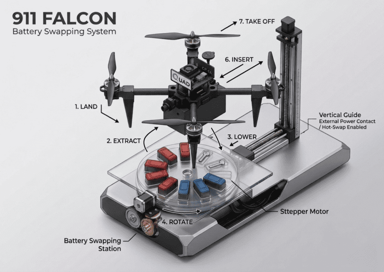
In the previous article, we covered one of the key features of the 911 FALCON system: the battery swap system — including its basic idea, overall structure, and operating sequence. We designed an automatic battery replacement system based on a station mounted on an autonomous ground vehicle, using X-axis and Z-axis linear actuators, a carousel structure, and a step motor. We also organized the full sequence in which the drone, after completing precision landing on the station, has its battery replaced via hot-swap while maintaining power to the aircraft.
In this article, we will move on to the next stage and cover the battery housing design process that makes the actual battery replacement possible. Starting from the basic housing configuration, we will go through each design element in order: power contact design, bolting position, camera and connector socket mounting holes, locking system, ideal diode, and ventilation holes — along with the structural considerations addressed at each step.
1. Design Overview
1-1) Why a Battery Housing Is Needed
The battery swap system of the 911 FALCON is designed so that the battery is inserted and removed using only the X-axis linear movement of the linear actuator. This means the battery cannot simply be connected to the drone directly. Instead, a dedicated interface structure was needed — one in which a single slide-in motion automatically engages the power contacts and securely locks the battery in place during flight.
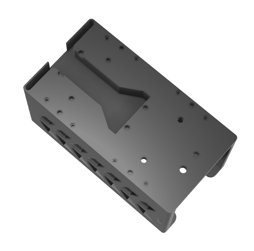
1-2) Housing Configuration
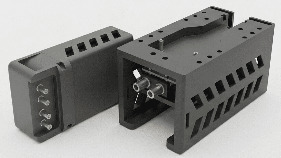
To meet these requirements, the housing is divided into two main parts: the Battery Housing and the Drone Housing.
- Battery Housing: Directly wired to the battery, it slides into and out of the Drone Housing together with the battery.
- Drone Housing: Fixed to the underside of the drone’s bottom plate, it serves as the receiving structure into which the Battery Housing is inserted and locked.
2. Power Contact Design — XT90 Terminal Approach
In a conventional drone, the battery is secured with a Velcro strap and powered by directly plugging in an XT connector. However, since the 911 FALCON requires the battery to be inserted and removed automatically via a linear actuator, a contact structure was needed in which power is automatically connected and disconnected through the slide-in motion alone.
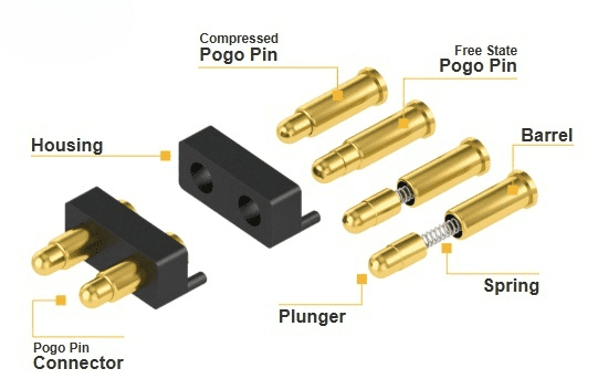
2-1) Pogo Pin Approach — Review and Limitations
Initially, we considered using Pogo Pins as the power contacts, as they are well-suited for slide-in connection mechanisms. Pogo pins use a spring-loaded structure that automatically makes contact upon insertion, making them a natural fit for this type of application.
However, the 911 FALCON drone consumes up to 200A of current when accounting for safety margins. Pogo pins are generally designed for signal-level currents in the range of a few amperes, making them unsuitable for reliably supplying this level of high current.
2-2) XT90 Terminal Approach
To resolve this, we adopted an approach in which the brass terminals from XT90 connectors are separated and used directly as the power contacts. XT90 terminals are widely used in the drone industry for high-current applications and can reliably handle current levels of up to 200A.
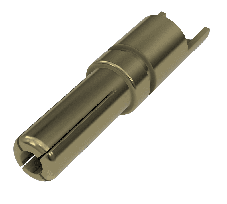
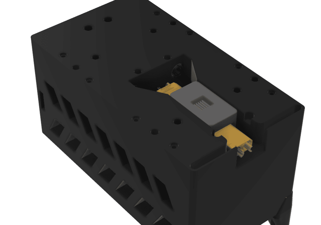
For the Battery Housing, a dedicated socket was designed so that the XT90 female terminal is precisely positioned and secured inside the housing.
The designed socket was then mounted into the Battery Housing, wired to the battery, and fixed in place by bolting.
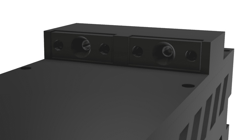
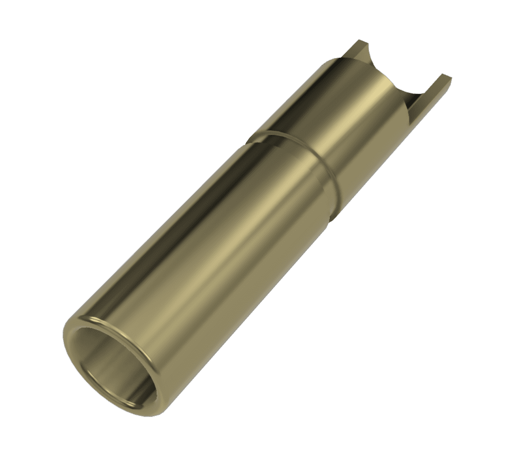
For the Drone Housing, a dedicated socket was similarly designed to hold the XT90 male terminal securely in the correct position.
The designed socket was bolted into the Drone Housing and then connected to the drone’s power module.
When the Battery Housing is slid into the Drone Housing, the male and female terminals automatically engage and power is supplied. Conversely, when the housing is pulled out, the terminals disengage and power is also disconnected.
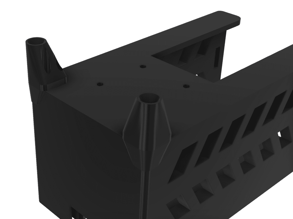
3. Bolting Position Design
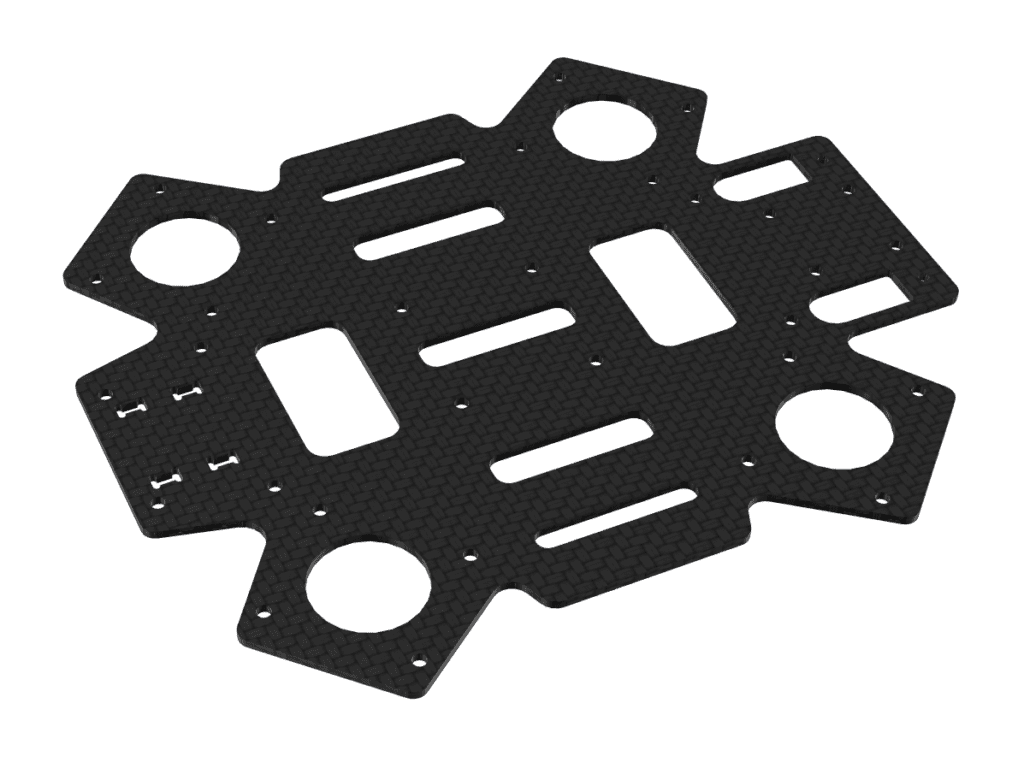
Conventional drone frames are designed around the assumption that batteries will be secured using a Velcro strap. As a result, the HTX415 frame does not include dedicated mounting holes for bolting a battery housing in place.
To work around this, we designed the Drone Housing to be fixed using the exposed thread ends of the bolts that secure the aluminum inserts and boom arms to the frame. Since the Battery Housing with the battery installed weighs over 2kg, the housing is secured with 2 bolts per side, and with 4 corners on the frame, a total of 8 bolts are used to fix the Drone Housing to the bottom plate.
Additionally, there are protruding structures on the underside of the drone’s bottom plate due to existing hardware. To allow the Drone Housing to sit flush against the bottom plate, relief cutouts were designed into the housing to avoid interference with these protrusions.
4. Downward Camera and Connector Socket Mounting Holes
Since the Drone Housing covers the underside of the drone’s bottom plate, dedicated mounting holes were required for components that need to be accessible from below. Two types of mounting holes were designed into the Drone Housing.
4-1) Downward Camera Mounting Hole
The 911 FALCON uses an Arducam 12.3MP IMX477 HQ Camera Module for precision landing, mounted facing downward. Since the Drone Housing covers the underside of the bottom plate, a camera mounting hole was designed into the housing to ensure the camera has an unobstructed downward field of view.
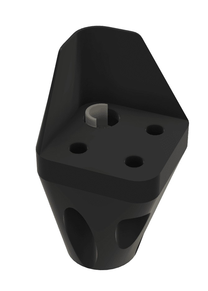
4-2) Hot-Swap Connector Socket Mounting Hole
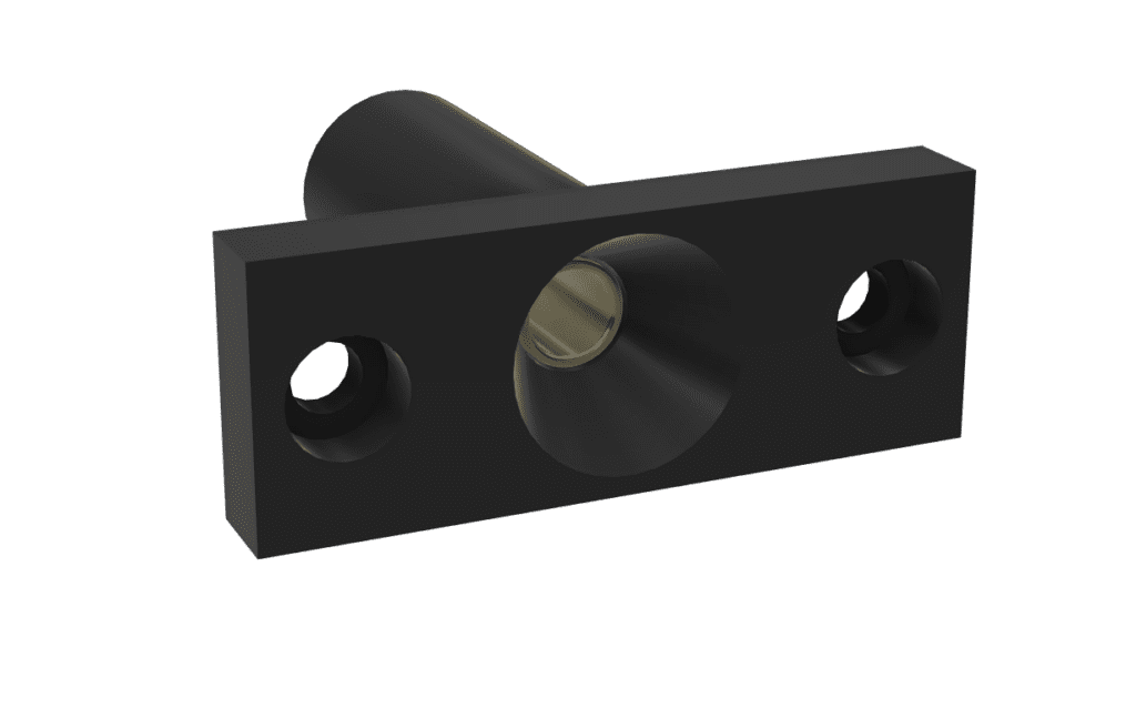
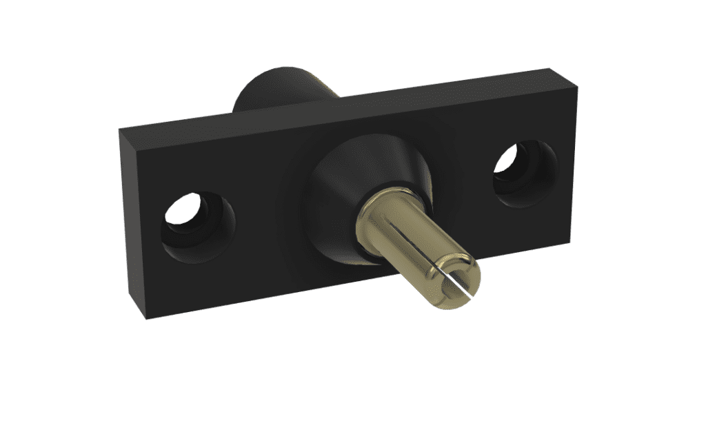
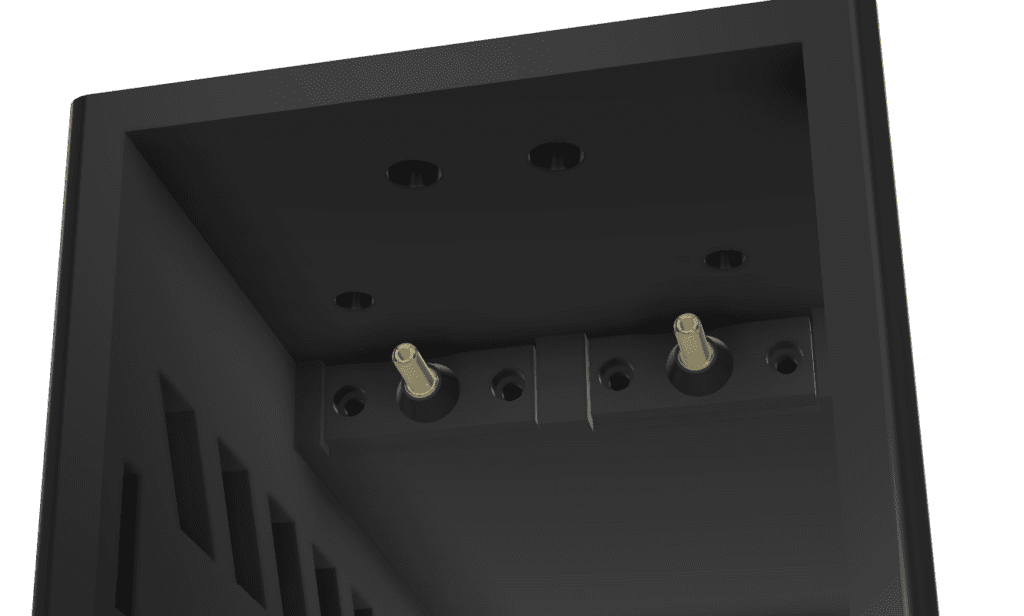
A mounting hole shaped to match the XT90 male terminal socket was designed into the Drone Housing to ensure the socket is precisely positioned and securely fixed inside the housing. Below is the hot-swap terminal socket that is bolted into the Drone Housing.
This terminal socket is fixed by bolting into the mounting hole of the Drone Housing, and is positioned so that the male and female terminals align precisely when the Battery Housing is slid in.
5. Locking System
During flight, vibration and inertial forces can cause the battery connection to loosen, and in severe cases, the battery may detach entirely. To prevent this, a pusher-spring locking system was designed.
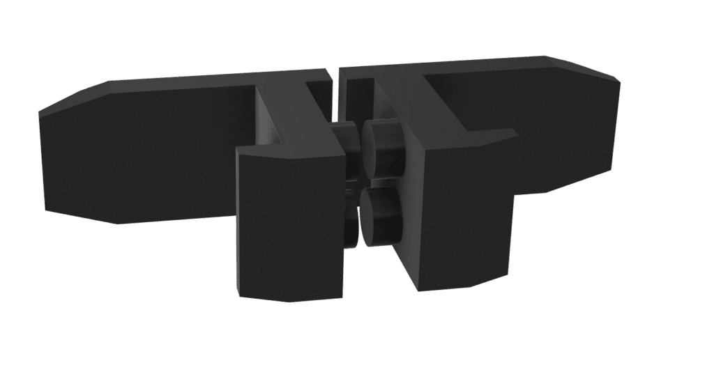
5-1) Structure
Latches are placed on both the left and right sides of the Battery Housing, connected to each other by a central compression spring. Under normal conditions, the spring pushes the two latches outward, keeping them extended beyond the outer edge of the Battery Housing.
5-2) Engagement Process
- Pressing both latches inward compresses the spring and brings the latches inside the housing profile.
- In this state, the Battery Housing is slid into the Drone Housing.
- Once fully inserted, releasing the latches allows the spring to extend, pushing the latches outward.
- The latches engage with recesses designed into the Drone Housing, completing the lock.
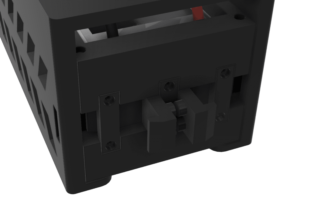
This structure ensures that even under vibration or inertial forces during flight, the Battery Housing remains securely locked and cannot separate from the Drone Housing.
6. Ideal Diode
6-1) Problem
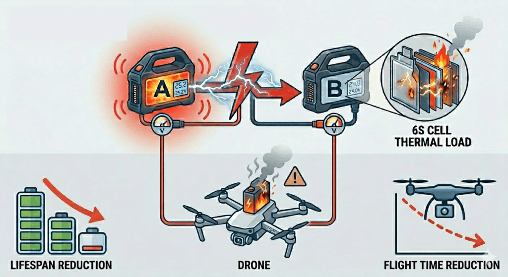
In the 911 FALCON hot-swap system, when the drone lands, the station’s power contacts engage with the Drone Housing terminals, and the station battery begins supplying power to the drone. Until the drone’s onboard battery is removed, there is a period during which the station battery and the drone battery are connected in parallel.
When two lithium batteries with a voltage difference are connected in parallel, a large inrush current flows instantaneously from the higher-voltage battery to the lower-voltage one. This places a sudden thermal load on the battery cells. If this rapid discharge occurs repeatedly, it can reduce battery lifespan by up to 30%. Furthermore, without protection circuitry, the higher-voltage battery effectively force-charges the lower-voltage one, which can lead to overcurrent, overheating, and in severe cases, battery explosion.
6-2) Solution — Ideal Diode
To prevent this, Ideal Diodes were incorporated into both the Drone Housing and the station’s battery docking housing.
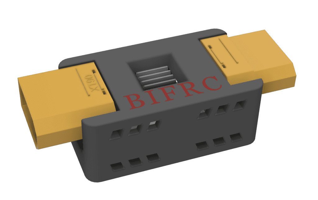
An Ideal Diode allows current to flow only from the battery outward, and blocks any current flowing back into the battery from an external source. This prevents reverse current flow due to voltage differences even when two batteries are simultaneously connected, safely protecting each battery.
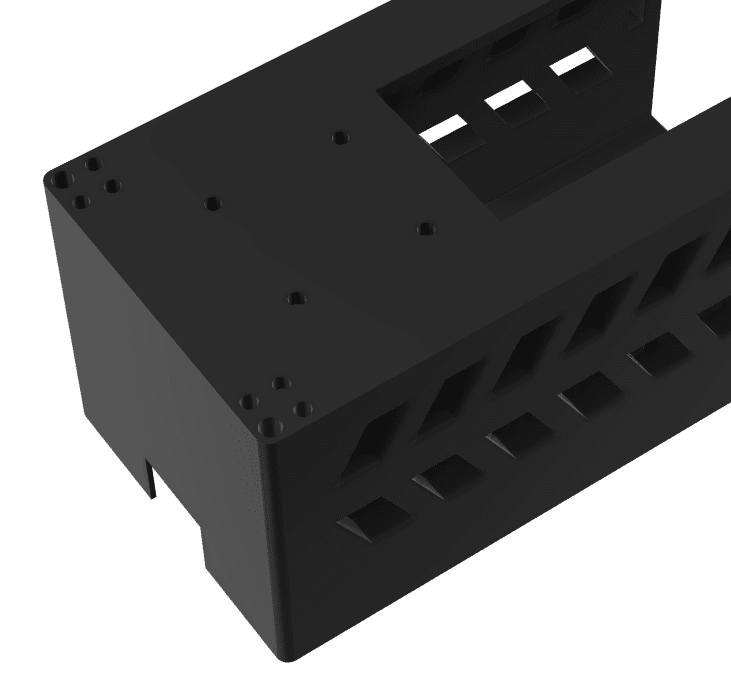
7. Battery Ventilation Holes
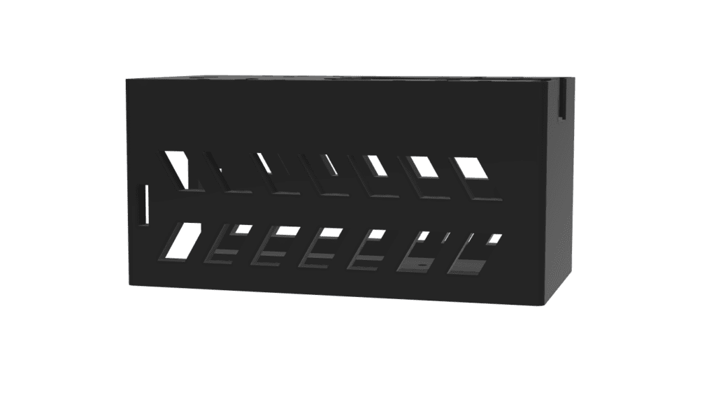
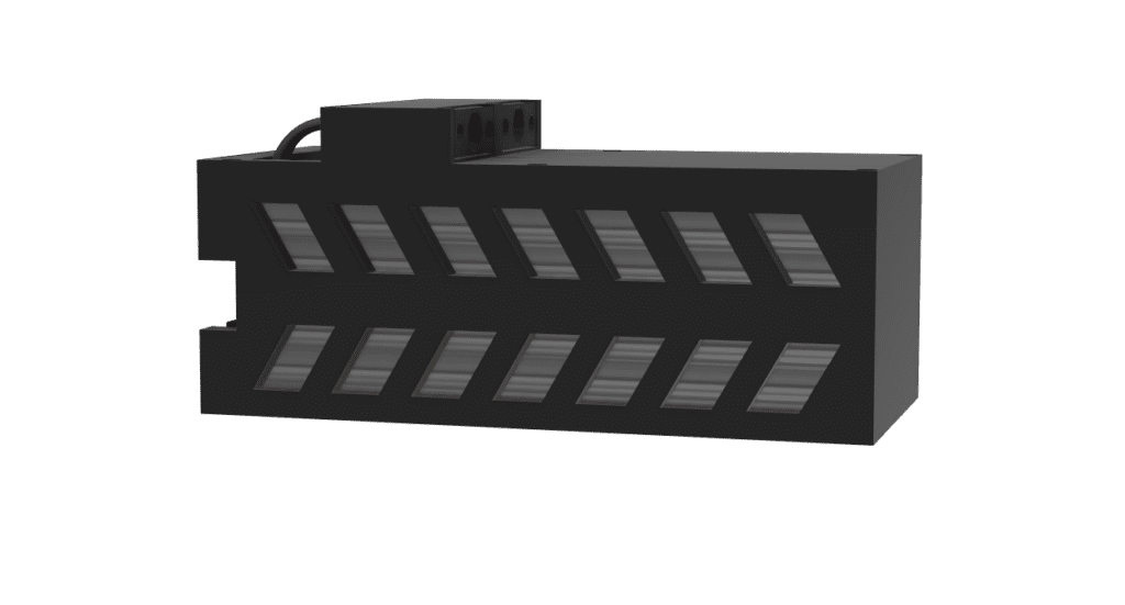
During flight, the battery continuously discharges at high current levels, generating significant heat. Since the battery is enclosed within the Battery Housing, there was a concern that heat would accumulate inside the housing without proper thermal management.
To address this, ventilation holes were designed into both the Battery Housing and the Drone Housing. The holes are positioned so that when the Battery Housing is fully engaged with the Drone Housing, the ventilation holes on both sides align, allowing airflow to pass through during flight and naturally dissipate the heat generated by the battery.
8. Structure Summary
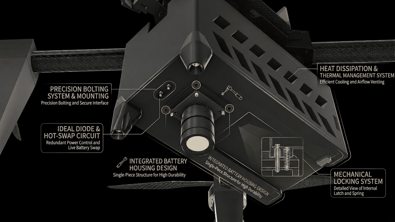
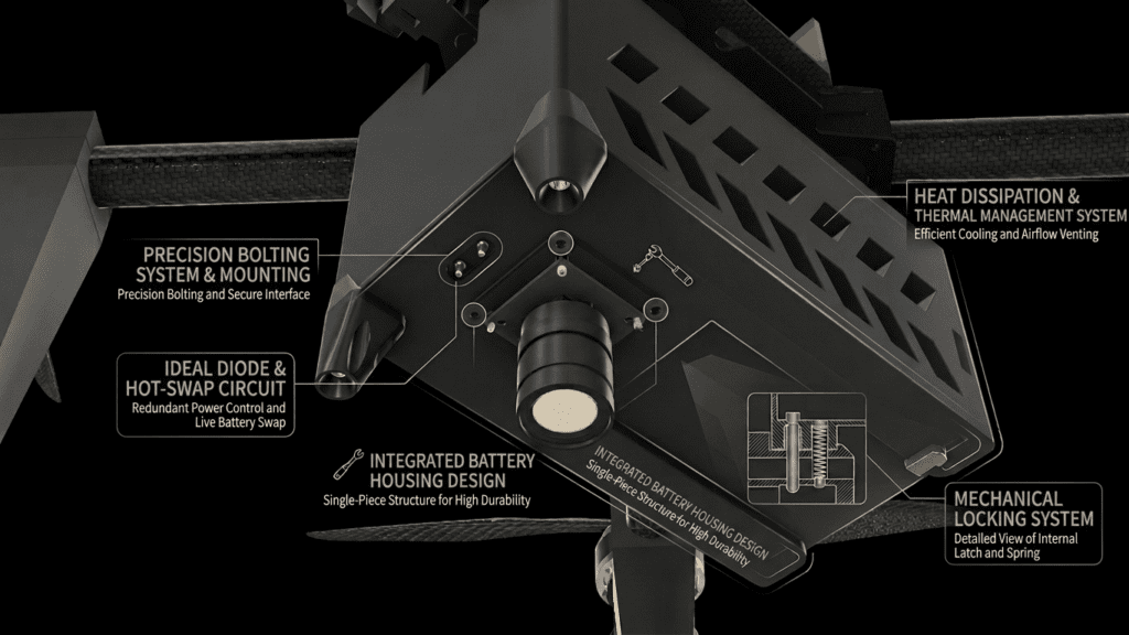
Below is a summary of the overall battery housing configuration designed in this article.
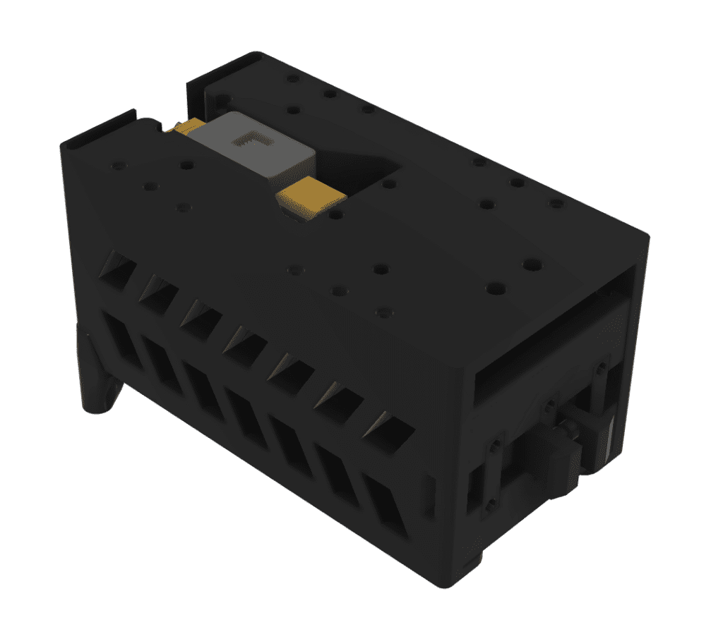
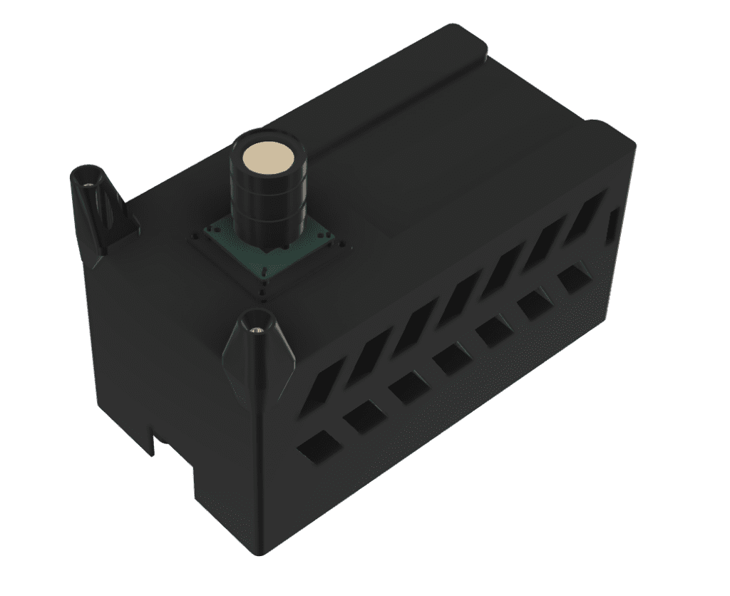
In the 911 FALCON drone, the Drone Housing is mounted to the underside of the drone’s bottom plate. The Battery Housing slides into the Drone Housing and is held in place by the locking system, preventing the battery from separating during flight. The underside of the Drone Housing also integrates the downward precision landing camera and the hot-swap terminal socket.
This article covered the battery housing design process for the 911 FALCON drone. From XT90 contact design and bolting structure to the locking system, ideal diode, and ventilation holes, all elements required for hot-swap operation were incorporated into the housing design at this stage.
In particular, the entire housing structure was designed around the constraint that battery insertion and removal must be achieved through X-axis linear movement alone — meaning that a single slide-in motion automatically engages the power contacts, locks the battery in place via the locking system, and enables heat dissipation all at once.
We will be taking a two-week break from the series. After the break, we will continue documenting the remaining stages of the 911 FALCON build. Thank you for reading.

Author: Guenchan lee, Senior Researcher of QUAD Drone Lab.
Date: April 14, 2026
![[MAVSDK C++ Part 4] Building Your Own App: Project Setup and Drone Connection](https://quad-drone-lab.co.kr/wp-content/uploads/2026/03/0314_인포그래피-768x512.png)
![PX4 MAVSDK – C++ Programming [Episode 11] Complete Comparison of MAVSDK vs MAVROS vs uXRCE-DDS](https://quad-drone-lab.co.kr/wp-content/uploads/2026/03/0322_인포그래피-768x512.png)
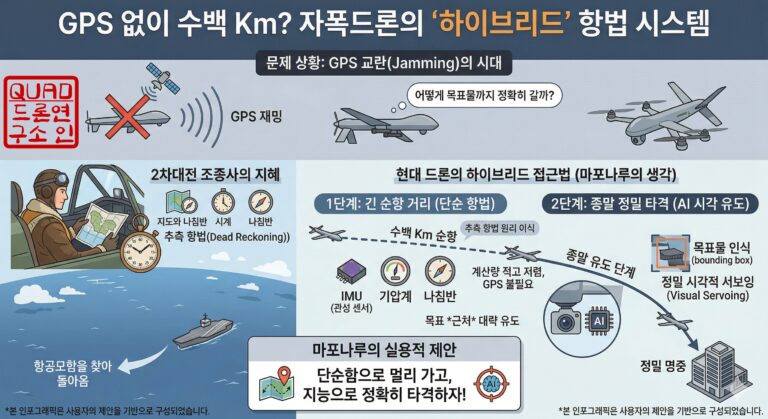
![[Hybrid Navigation System Series Part 1: Overview] Flying Hundreds of Kilometers Without GPS? Learning a Hybrid Navigation System from WWII Pilots](https://quad-drone-lab.co.kr/wp-content/uploads/2026/04/컴패니언-컴퓨터-기반의-AI-지형지물-보정-768x419.jpg)