PX4 MAVLink-Python Programming: 1. MAVLink Overview
MAVLINK Overview
Hello, this is Aiden from the marketing team.
Today, I will be introducing PX4 MAVLink-Python Programming, starting with an overview of MAVLink. This content is the registered intellectual property of QUAD Drone Research Lab. We kindly request that you do not distribute it without prior authorization.

YouTube Tutorial
Please follow the steps below along with the YouTube video.
A. MAVLink Protocol
MAVLink is the most commonly used serial protocol for transmitting data and commands between drones and Ground Control Stations (GCS).
This protocol defines an extensive set of messages that can be found in common.xml and ardupilot.xml. MAVLink messages can be transmitted over almost any serial connection and are independent of the underlying technology (e.g., WiFi, 900MHz radio).
Since message delivery is not guaranteed, the Ground Control Station or companion computer must often verify the vehicle’s status to confirm that commands have been executed.
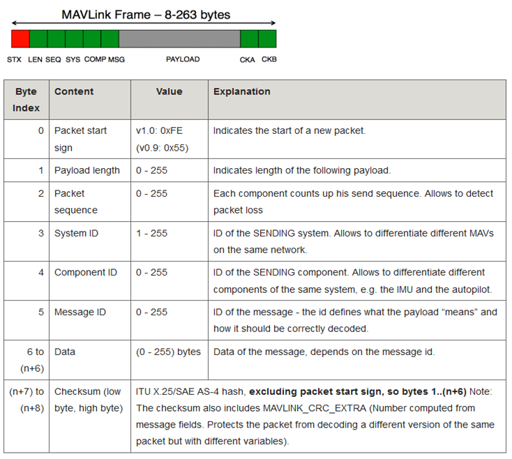
- Messages do not exceed 263 bytes.
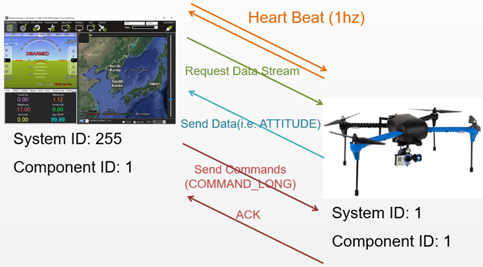
- The sender always populates the System ID and Component ID fields so that the receiver can identify the source of the packet. The System ID must be a unique ID for each vehicle or ground station. Ground stations typically have a high System ID (255), while vehicles have a default value of “1.” These values are configurable. The Component ID defaults to “1” for both the ground station and the vehicle. Multiple different MAVLink devices on the same vehicle (e.g., companion computer, gimbal, etc.) must share the same System ID but have different Component IDs.
- The Message ID field can be found next to the message name in
common.xmlandardupilot.xml. For example, the Message ID for theHEARTBEATmessage is “0.” - The Data section holds the individual field values being transmitted.
- Please refer to this page for advice on how to add support for new MAVLink messages.
B. Communication Flow
Once the connection is established, each device (also referred to as a “System”) sends a HEARTBEAT message at a rate of 1Hz.
The ground station or companion computer requests the desired data (and the frequency) by sending the following types of messages:
REQUEST_DATA_STREAMsupports setting the rate for specific groups of messages.COMMAND_LONG, which includes theSET_MESSAGE_INTERVALcommand, allows for precise control over which messages are transmitted and at what rate. However, this is only supported in ArduPilot 4.0 or higher.
The ground station or companion computer then sends the commands to the vehicle.
C. MAVLink1 vs. MAVLink2
MAVLink2 extends MAVLink1 to allow the addition of new fields to existing MAVLink1 messages, supports new Message IDs above “255,” and adds support for message signing (authentication).
MAVLink2 is backward compatible with MAVLink1. If a device that only understands MAVLink1 receives a message containing extra fields (added in MAVLink2), the device will only see the original fields. In other words, the device can read the message but cannot see the additional fields.
You can enable MAVLink2 on the flight controller’s serial port (likely connected to a telemetry radio) by setting the SERIALx_PROTOCOL parameter to “2.”
MAVLink 1 vs. MAVLink 2 Packet Comparison
The following is the wire format of the MAVLink 2 packet (the in-memory representation may vary):
MAVLINK v2 packet
| Byte Index | C version | Content | Value | Explanation |
|---|---|---|---|---|
| 0 | uint8_t magic | Packet start marker | 0xFD | This is the protocol-specific Start-of-Text (STX) marker used to indicate the beginning of a new packet. Systems that do not recognize the protocol version will skip the packet. |
| 1 | uint8_t len | Payload length | 0 – 255 | Indicates the length of the following Payload section. This may be affected by payload truncation. |
| 2 | uint8_t incompat_flags | Incompatibility Flags | Flags that must be understood for MAVLink compatibility (the implementation will drop the packet if it does not recognize these flags). | |
| 3 | uint8_t compat_flags | Compatibility Flags | Flags that can be ignored if not understood (the implementation can still process the packet even if it does not recognize these flags). | |
| 4 | uint8_t seq | Packet sequence number | 0 – 255 | Used to detect packet loss. The component increments this value for each message sent. |
| 5 | uint8_t sysid | System ID (sender) | 1 – 255 | The ID of the system (vehicle) sending the message. It is used to distinguish systems on the network. A broadcast address of 0 is an invalid source address and cannot be used in this field. |
| 6 | uint8_t compid | Component ID (sender) | 1 – 255 | The ID of the component sending the message. It is used to distinguish between components within a system (e.g., the autopilot and the camera). Please use the appropriate values from MAV_COMPONENT. The broadcast address MAV_COMP_ID_ALL is an invalid source address and cannot be used in this field. |
| 7 to 9 | uint32_t msgid:24 | Message ID (low, middle, high bytes) | 0 – 16777215 | The Message Type ID of the payload. It is used to decode the data back into a message object. |
For n-byte payload:n=0: NA, n=1: 10, n>=2: 10 to (9+n) | uint8_t payload[max 255] | Payload | Message data. The content depends on the message type (i.e., Message ID). | |
| (n+10) to (n+11) | uint16_t checksum | Checksum (low byte, high byte) | CRC-16/MCRF4XX for the message (excluding the magic byte). It includes the CRC_EXTRA byte. | |
| (n+12) to (n+25) | uint8_t signature[13] | Signature | (Optional) Signature for link tamper protection. |
- For an acknowledgement packet with no payload, the minimum packet length is 12 bytes.
- The maximum packet length for a signed message using the full payload is 280 bytes.
MAVLink 1 Packet Format
The following is the wire format of the MAVLink 1 packet (the in-memory representation may vary).
MAVLINK v1 packet
| Byte Index | C version | Content | Value | Explanation |
|---|---|---|---|---|
| 0 | uint8_t magic | Packet start marker | 0xFE | This is the protocol-specific Start-of-Text (STX) marker used to indicate the beginning of a new packet. Systems that do not recognize the protocol version will skip the packet. |
| 1 | uint8_t len | Payload length | 0 – 255 | Indicates the length of the following Payload section (fixed for a specific message). |
| 2 | uint8_t seq | Packet sequence number | 0 – 255 | Used to detect packet loss. The component increments this value for each message sent. |
| 3 | uint8_t sysid | System ID | 1 – 255 | The ID of the system (vehicle) sending the message. It is used to distinguish systems on the network. A broadcast address of 0 is an invalid source address and cannot be used in this field. |
| 4 | uint8_t compid | Component ID | 1 – 255 | The ID of the component sending the message. It is used to distinguish between components within a system (e.g., the autopilot and the camera). Please use the appropriate values from MAV_COMPONENT. The broadcast address MAV_COMP_ID_ALL is an invalid source address and cannot be used in this field. |
| 5 | uint8_t msgid | Message ID | 0 – 255 | The Message Type ID of the payload. It is used to decode the data back into a message object. |
For n-byte payload:n=0: NA, n=1: 6, n>=2: 6 to (5+n) | uint8_t payload[max 255] | Payload data | Message data. The content depends on the message type (i.e., Message ID). | |
| (n+6) to (n+7) | uint16_t checksum | Checksum (low byte, high byte) | CRC-16/MCRF4XX for the message (excluding the magic byte). It includes the CRC_EXTRA byte. |
- The minimum packet length for an acknowledgement packet with no payload is 8 bytes.
- The maximum packet length for a full payload is 263 bytes.
This concludes the first step of PX4 MAVLink-Python programming: the MAVLink Overview. In the next post, we will return with a guide on how to use the Python MAVLink library (pymavlink). As this is the foundational stage, we recommend reviewing these packet structures and protocols thoroughly.

Author: Aiden, Marketing Team at QUAD Drone Lab
Date: February 23, 2026
![[하이브리드 항법 시스템 제1편: 개요] GPS 없이 수백 km를 날아간다? 2차대전 조종사에게 배우는 하이브리드 항법 시스템](https://quad-drone-lab.co.kr/wp-content/uploads/2026/04/컴패니언-컴퓨터-기반의-AI-지형지물-보정-768x419.jpg)
![PX4 MAVSDK – C++ Programming [7편] 특정 위치로 이동 (goto_location) 및 하버사인 공식의 이해](https://quad-drone-lab.co.kr/wp-content/uploads/2026/03/0317_인포-768x512.png)
![PX4 MAVSDK – C++ Programming [12편] MAVSDK C++를 활용한 최신 자율 비행 연구 사례](https://quad-drone-lab.co.kr/wp-content/uploads/2026/03/0322_인프그래피2-768x429.jpg)
![[하이브리드 항법 시스템: 제3편] 산업용 고성능 INS(관성항법장치) 이해와 GPS 교란 시뮬레이터 만들기](https://quad-drone-lab.co.kr/wp-content/uploads/2026/04/Physics-of-IMU-Drift-Errors-1-768x429.jpg)
![[하이브리드 항법 시스템: 특별편] GPS 교란을 버텨라! PX4 Dead-Reckoning (추측 항법) 모드 완벽 가이드](https://quad-drone-lab.co.kr/wp-content/uploads/2026/05/Resilient_Drone_Dead-Reckoning_Navigation-768x429.jpg)