2-Axis Servo Gimbal Design and Wiring : 911 FALCON Project
Hello, this is QUAD Drone Laboratory.
I’m Geunchan Lee, Senior Researcher at QUAD Drone Lab.
In the previous article, we covered the video transmitter, OSD, and camera wiring and setup process for the 911 FALCON drone. Due to PX4 firmware’s lack of native analog OSD support, the Holybro Micro OSD V2 module was used to receive flight data from the FC via MAVLink protocol and overlay it onto the analog video feed. The process was carried out in order from wiring to QGC parameter settings, OSD Configurator setup, and PAL/NTSC video mode troubleshooting.
In this article, we will cover the 2-axis servo gimbal design and wiring process using MG90 servo motors. We will go through the differences from the reference design, the design process for each Pan and Tilt mount, and the concentric pin-hole rotation axis implementation in order.
1. Design Overview
1-1) Reference Design
https://www.youtube.com/watch?v=CBHTAzudm68&t=240s
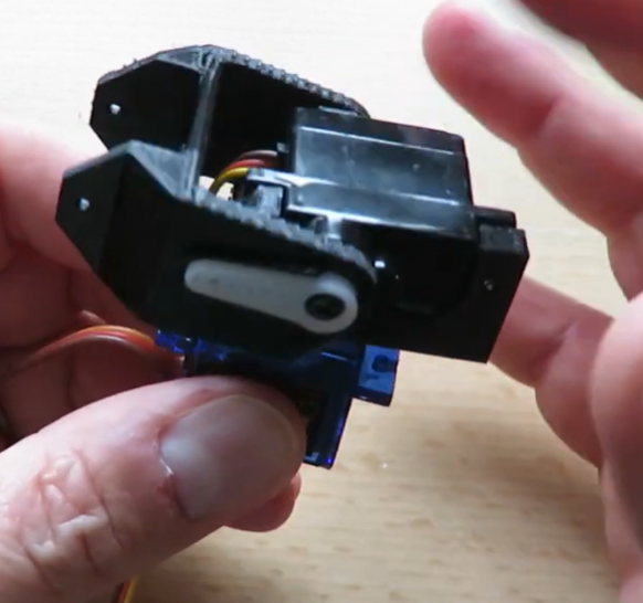
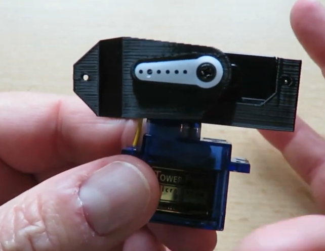
The gimbal design was based on a reference from Painless360‘s 2-axis servo tilt gimbal build video. The video can be viewed via the YouTube link below the image.
The reference design places the Pan axis (left-right rotation) servo at the bottom as the base, mounts the Tilt axis (up-down rotation) servo on top, and attaches the camera in front of the Tilt servo. This approach is structurally stable with low load on the servo motors, as the distance between the first rotation axis (Z-axis) and the camera is short. However, since the Tilt axis components are stacked vertically, the overall height becomes larger.
1-2) 911 FALCON Approach
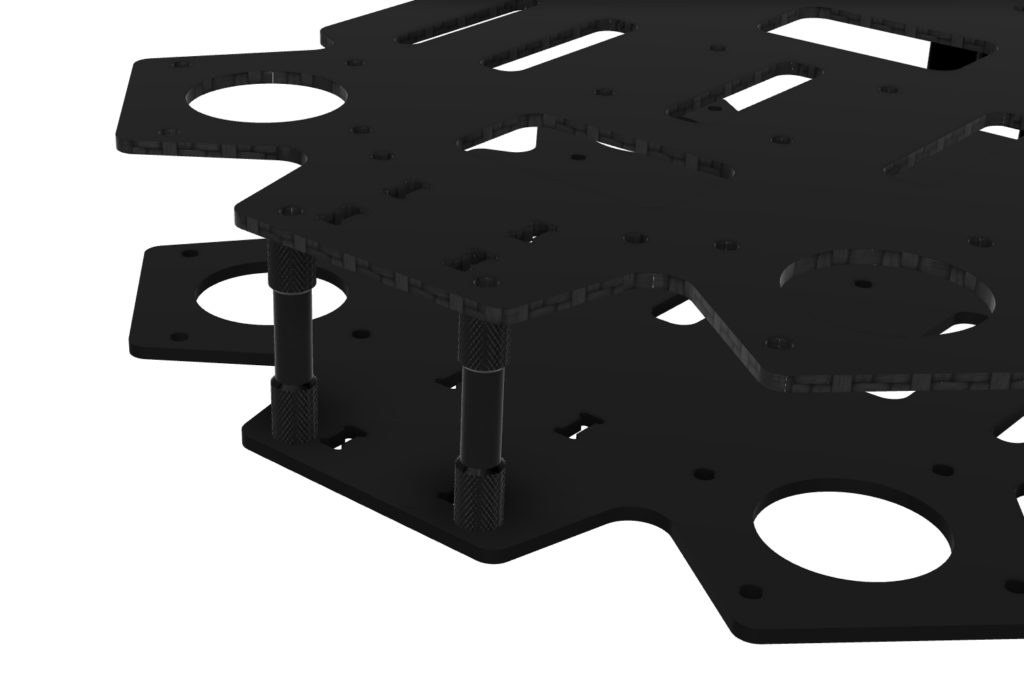
Since the gimbal needed to fit within the limited frame space of the 911 FALCON airframe, the reference design could not be applied directly. The servo placement was therefore modified — the Pan axis servo is placed at the rear and the Tilt axis servo is placed in front of it. The camera is connected directly to the Tilt servo horn and driven up and down. This allowed the overall height to be reduced and the gimbal to fit within the frame space.
2. Gimbal Structure Design
2-1) Pan Servo Mount
Placement
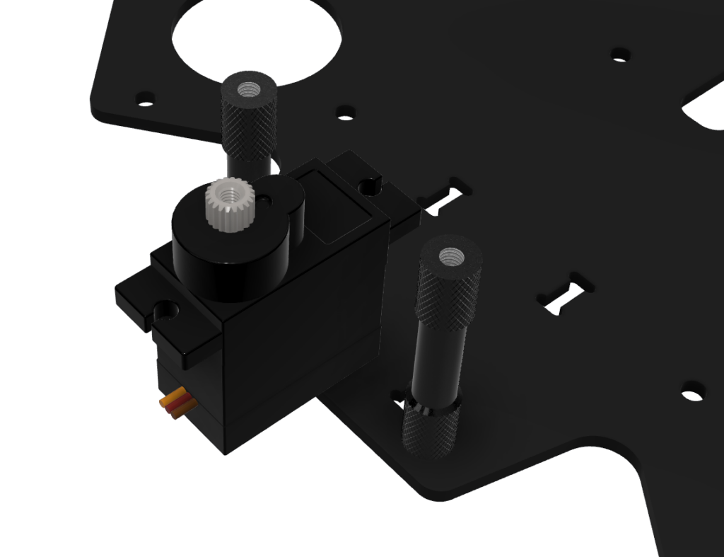
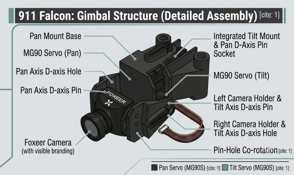
The Pan axis servo is placed at the rearmost position of the gimbal. The entire Pan-Tilt mount is installed by fitting into the front standoffs of the airframe, with the Pan servo inserted and secured inside the mount.
Design
Step 1 — Servo Insertion Space Design
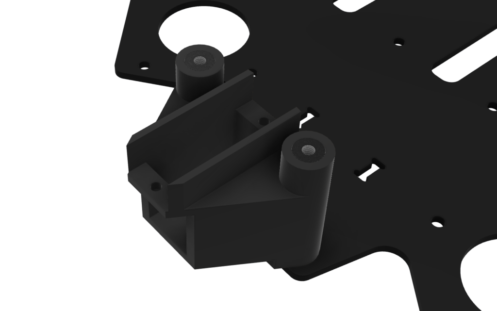
The Pan servo mount was designed with the frame space and servo motor dimensions considered together. The mount was designed so that the servo can be precisely inserted and secured inside. The Pan servo horn is exposed outside the mount and engages with the servo horn socket of the Tilt mount to transmit rotation.
Step 2 — Circular Pin Design

The servo horn alone cannot secure the Tilt mount, and stable rotation is also difficult to achieve. While the servo horn transmits rotation, without the opposite side being fixed, the mount may wobble or detach. To address this, a circular pin was designed at the same position as the Pan servo’s rotation center. This pin engages with the circular hole of the Tilt mount, securing the Tilt mount while simultaneously forming a rotation axis. The pin must be positioned at the same location as the Pan servo’s rotation center so that the Tilt mount shares the same rotation center.
2-2) Tilt Servo Mount
Placement
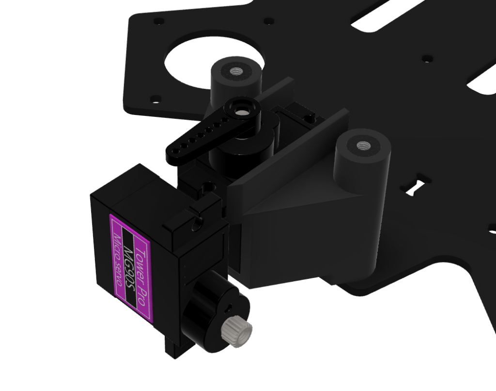
The Tilt axis servo is placed in front of the Pan servo. The Tilt servo mount is designed as a single structure that is driven left and right by the Pan servo horn, while simultaneously driving the camera up and down via the Tilt servo inserted inside.
Design — Pan Mount Connection
Step 1 — Servo Horn Socket and Circular Hole Design
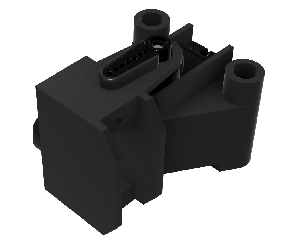
On the upper side (servo horn socket side), a servo horn socket for the Pan servo was designed. When the Pan servo horn engages with this socket, the rotation of the Pan servo is transmitted to the entire Tilt mount, driving it left and right.

To support this rotation stably, a circular hole into which the Pan mount’s circular pin fits was designed on the lower side (circular hole side). This circular hole engages with the Pan mount’s circular pin, securing the Tilt mount while simultaneously forming a rotation axis on the opposite side from the servo horn socket. The circular hole was designed with appropriate clearance so that it fits concentrically with the pin while still allowing rotation.
The length of the arm connecting the upper socket and lower hole determines the gap between the Pan mount and Tilt mount. If the distance is too close, interference during rotation will limit the rotation angle. If it is too far, the arm length from the fixed point to the camera increases, causing greater torque and instability. The arm length was therefore designed to secure sufficient rotation space while keeping the two mounts as close as possible.
Design — Camera Holder Connection
Step 1 — Tilt Servo Insertion Space Design
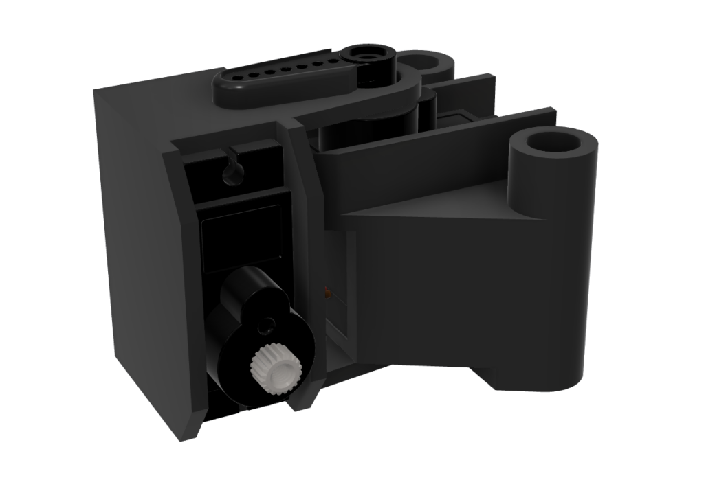
To drive the camera up and down, the Tilt servo is designed to be inserted sideways from the left side of the mount. The mount was designed so that the servo can be precisely inserted and secured on the left side. The Tilt servo horn is exposed outside the mount and engages with the servo horn socket of the camera holder to transmit rotation.
Step 2 — Circular Pin Design
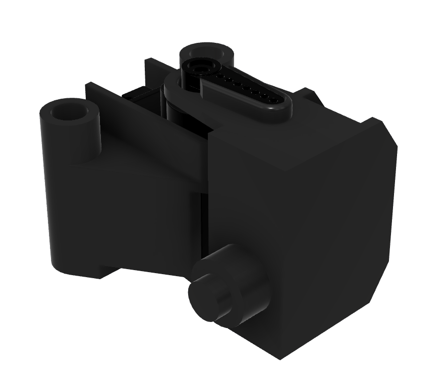
The servo horn alone cannot secure the camera holder, and stable rotation is also difficult to achieve. While the servo horn transmits rotation, without the opposite side being fixed, the camera holder may wobble or detach. To address this, a circular pin was designed at the same position as the Tilt servo’s rotation center on the right side of the mount. This pin engages with the circular hole of the camera holder, securing the camera holder while simultaneously forming a rotation axis. The pin must be positioned at the same location as the Tilt servo’s rotation center so that the camera holder shares the same rotation center.
Step 3 — Signal Wire Outlet Hole Design
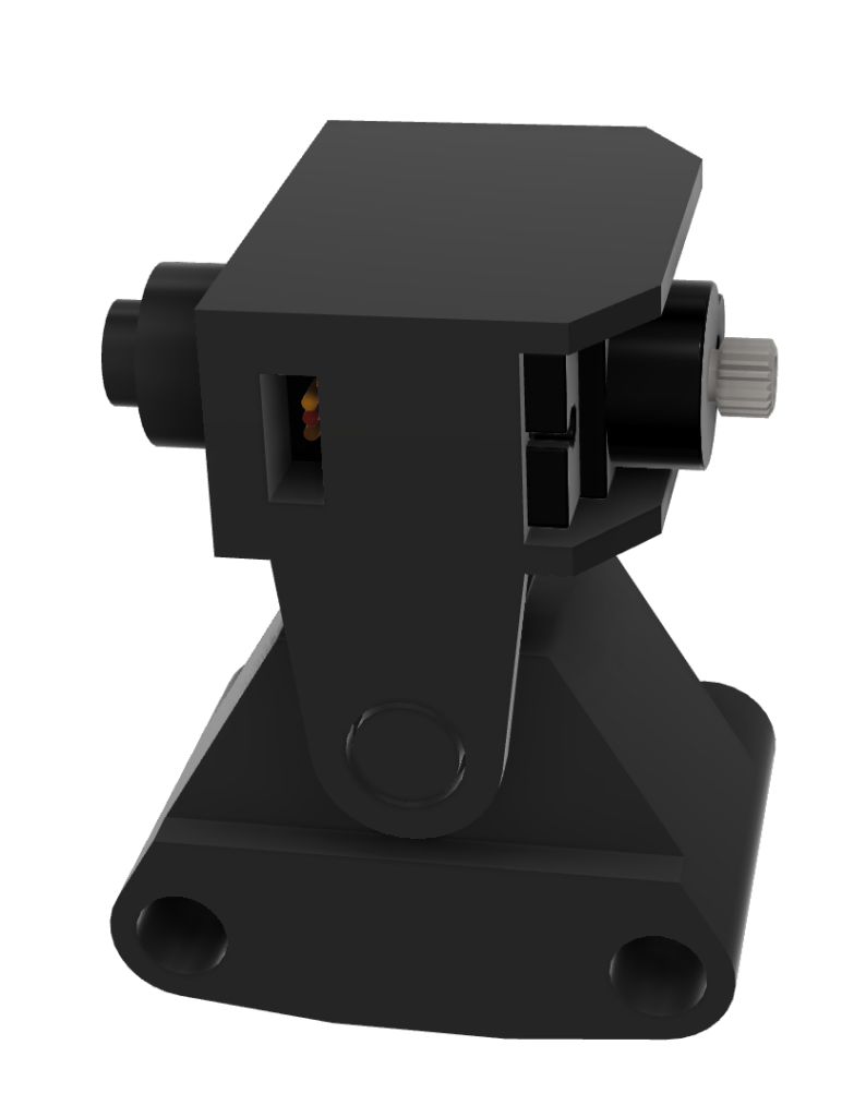
A hole was designed to allow the Tilt servo’s signal wire to be routed outside the mount.
2-3) Camera Holder
Placement
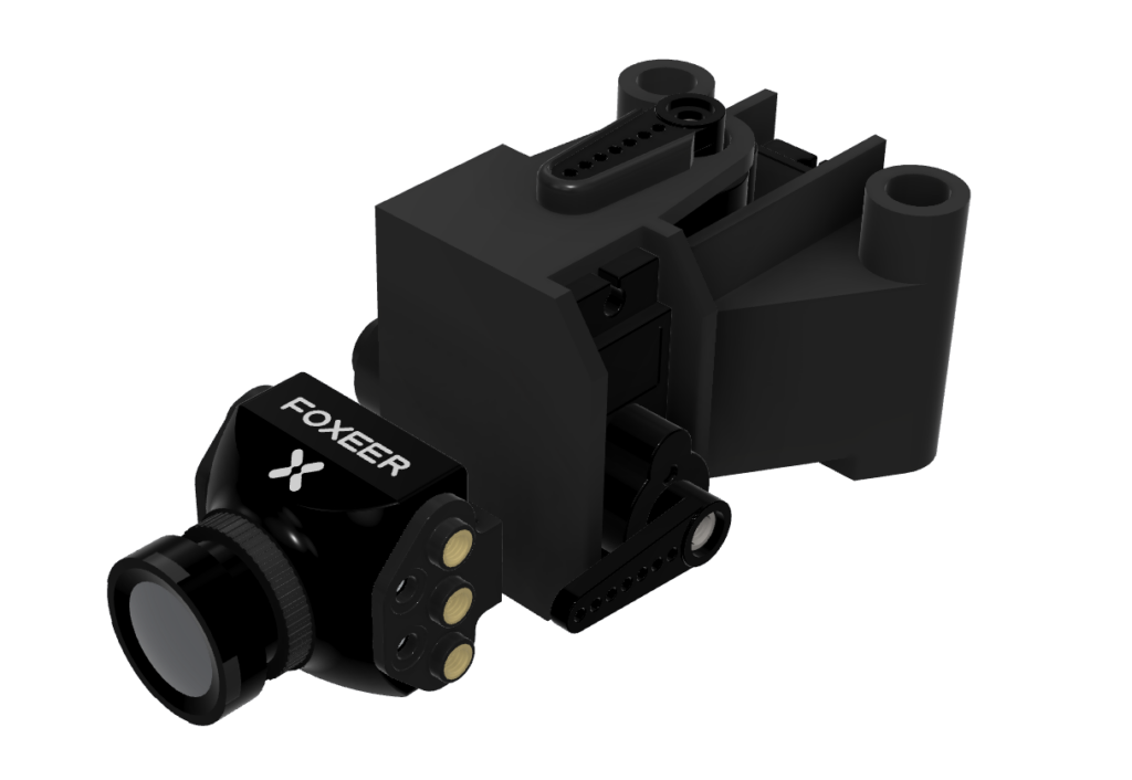
The camera holder is placed in front of the Tilt servo and is driven up and down by the rotation of the Tilt servo horn. The camera holder consists of left and right two parts.
Design
Step 1 — Left Holder: Servo Horn Socket and Right Holder: Circular Hole Design
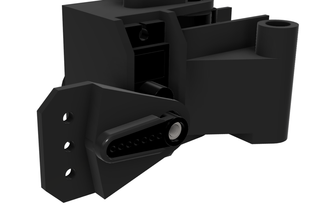
The left camera holder was designed with a servo horn socket for the Tilt servo. When the Tilt servo horn engages with this socket, the rotation of the Tilt servo is transmitted to the entire camera holder, driving it up and down.
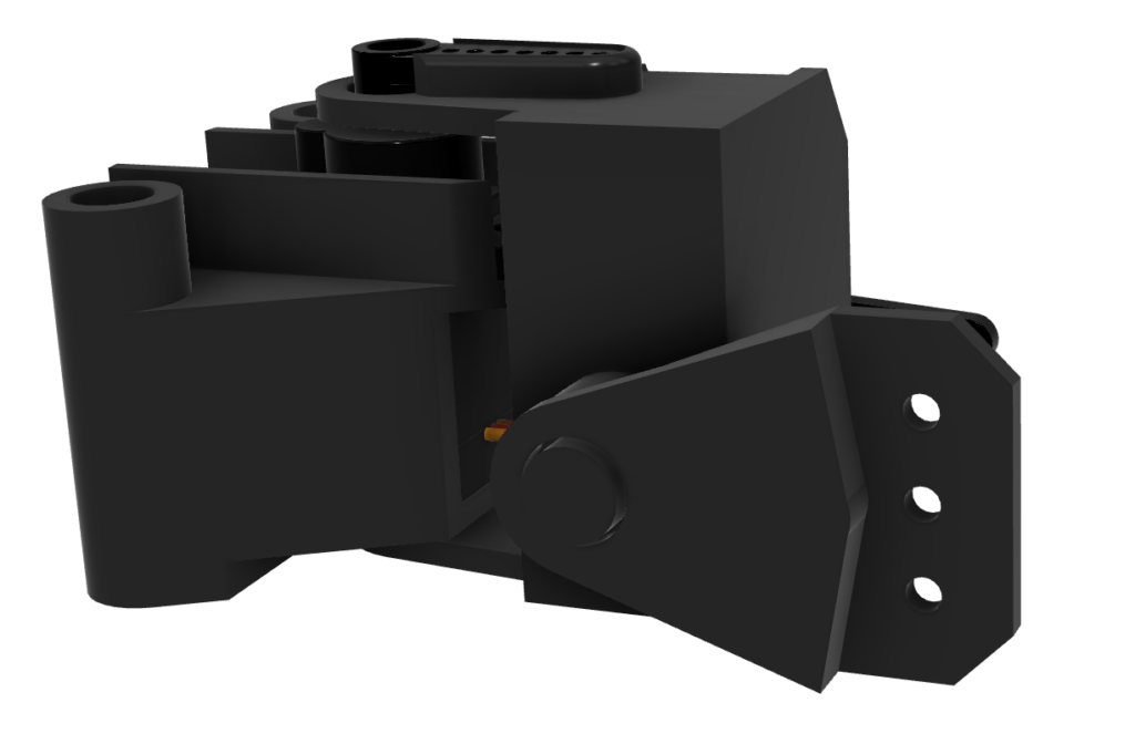
To support this rotation stably, the right camera holder was designed with a circular hole into which the Tilt mount’s circular pin fits. This circular hole engages with the Tilt mount’s circular pin, securing the camera holder while simultaneously forming a rotation axis on the opposite side from the servo horn socket. The circular hole was designed with appropriate clearance so that it fits concentrically with the pin while still allowing rotation.
The length of the arm connecting the left socket and right hole determines the gap between the Tilt mount and camera holder. Similarly, the arm length was designed to secure sufficient rotation space while keeping the gap as small as possible.
Step 2 — Camera Mounting
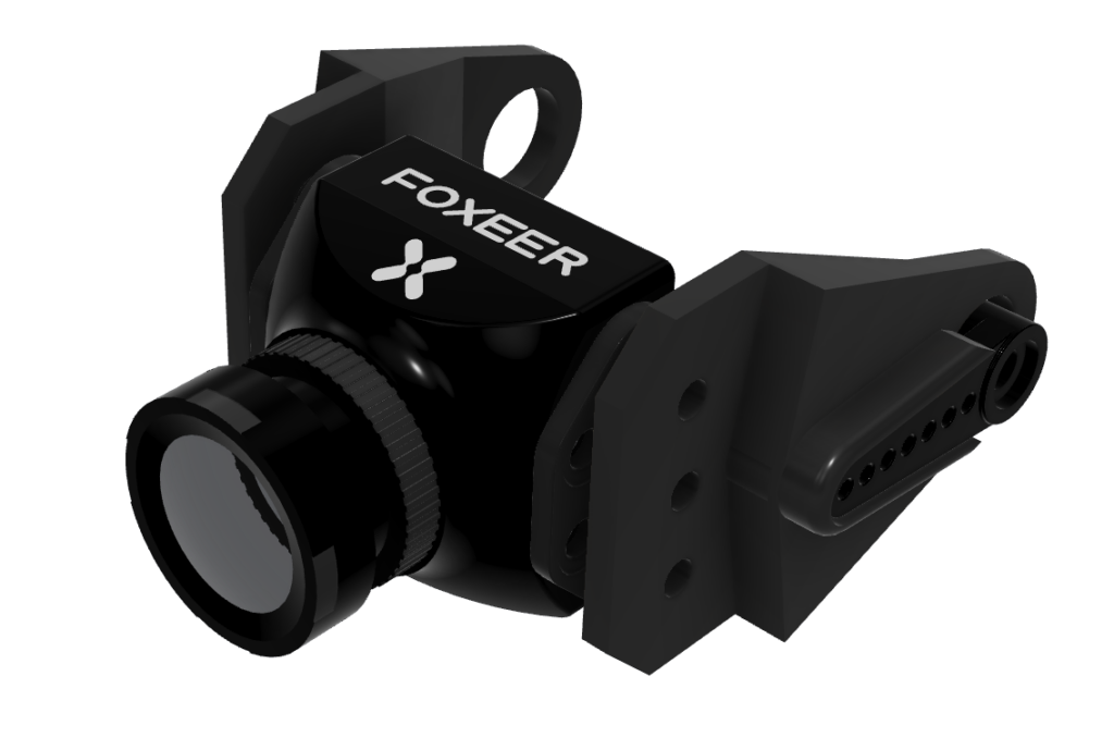
Both the left and right holders were designed to mount onto the camera’s mounting holes. The servo horn socket and the opposite circular hole were designed to be at the same position relative to the origin, ensuring that the tilting axis does not wobble during rotation.
3. Wiring
The servo motor wiring is connected through the FC’s AUX ports.
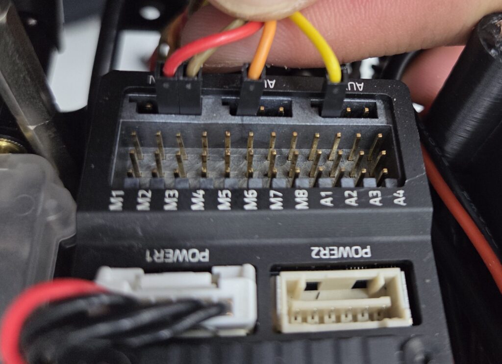
- Pan axis servo signal wire → AUX port 6
- Tilt axis servo signal wire → AUX port 5
- Power: drawn from the FC’s RC IN port, with both servos connected in parallel
4. Print and Install
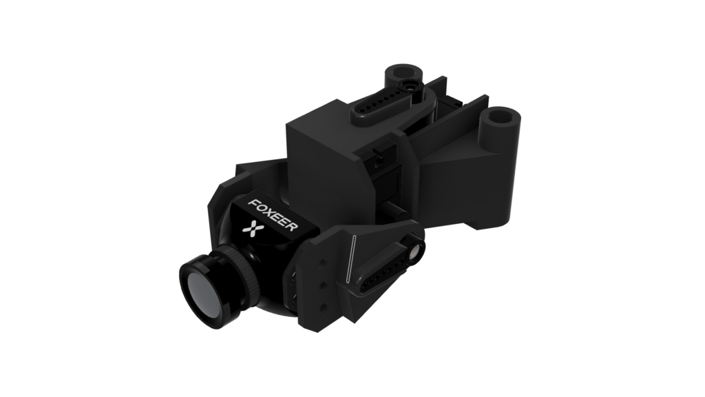
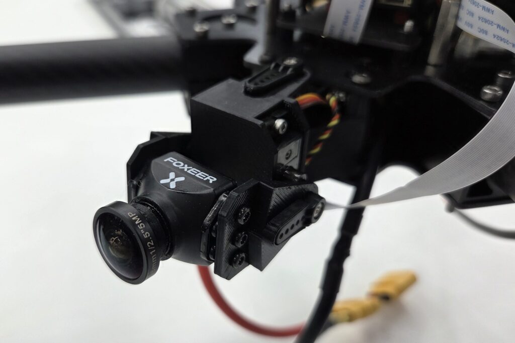
After 3D printing the designed Pan·Tilt 2-axis gimbal and mounting it to the front of the airframe, a structure capable of freely controlling the pilot’s field of view was completed. By independently adjusting the camera angle through the left-right Pan axis and up-down Tilt axis, the system enables efficient search coverage over a wide area. Additionally, during takeoff and landing, the Tilt axis can be used to point the camera downward, allowing direct visual confirmation of the landing spot, which is also useful for precise takeoff and landing operations.
This article covered the 2-axis servo gimbal design and wiring process for the 911 FALCON drone. Based on the differences from the reference design, the gimbal was designed to fit within the airframe’s frame space, and the 2-axis gimbal structure using Pan and Tilt servos along with the concentric pin-hole rotation axis implementation were organized.
In the next article, we will cover the head tracking implementation process based on the gimbal structure completed in this article. Starting from servo AUX channel configuration in PX4, we will go through the process of implementing head tracking using the trainer signal from the goggles and transmitter. Thank you for reading.

Author: Guenchan lee, Senior Researcher of QUAD Drone Lab.
Date: July 15, 2026
![[PX4 Tuning Series 6] Trajectory Generator and Setpoint Tuning: The Art of Flight Feel and Smooth S-Curves](https://quad-drone-lab.co.kr/wp-content/uploads/2026/03/Drone-Trajectory-Comparison-768x429.png)
![[Hybrid Navigation System: Special Edition] Survive GPS Jamming! A Complete Guide to “PX4 Dead-Reckoning Mode”](https://quad-drone-lab.co.kr/wp-content/uploads/2026/05/Resilient_Drone_Dead-Reckoning_Navigation-768x429.jpg)
![[Everything About Drone Batteries] Part 1: Drone Battery Fundamentals and Chemical Characteristics: LiPo vs. Li-Ion](https://quad-drone-lab.co.kr/wp-content/uploads/2026/04/Drone-Battery-Anatomy-and-Assembly-768x429.jpg)
![[Hybrid Navigation System: Part 6] [Implementation-Phase 2] Intermediate Correction: OpenCV/YOLO Terrain Matching and Digital Twin Testing](https://quad-drone-lab.co.kr/wp-content/uploads/2026/06/Absolute_Visual_Localization_for_UAVs-768x429.jpg)