

Motor and ESC Wiring, Arming and Throttle Check : 911 FALCON Project
Hello, this is QUAD Drone Laboratory.
I’m Geunchan Lee, Senior Researcher at QUAD Drone Lab.
In the previous article, we covered the receiver wiring and setup process for the 911 FALCON drone. Starting from transmitter channel configuration and ELRS version verification, we proceeded through receiver wiring, firmware update, and binding, followed by FC parameter settings, RC calibration, and flight mode configuration.
In this article, we will cover the motor and ESC wiring process and arming and throttle operation verification. We will go through the power wiring between the PDB and ESC, motor wiring, signal wire connections to the FC, motor direction configuration, and finally confirm arming and throttle operation via the transmitter.
1. ESC and Motor Wiring
1-1) Power Wiring (Power Module → PDB → ESC)

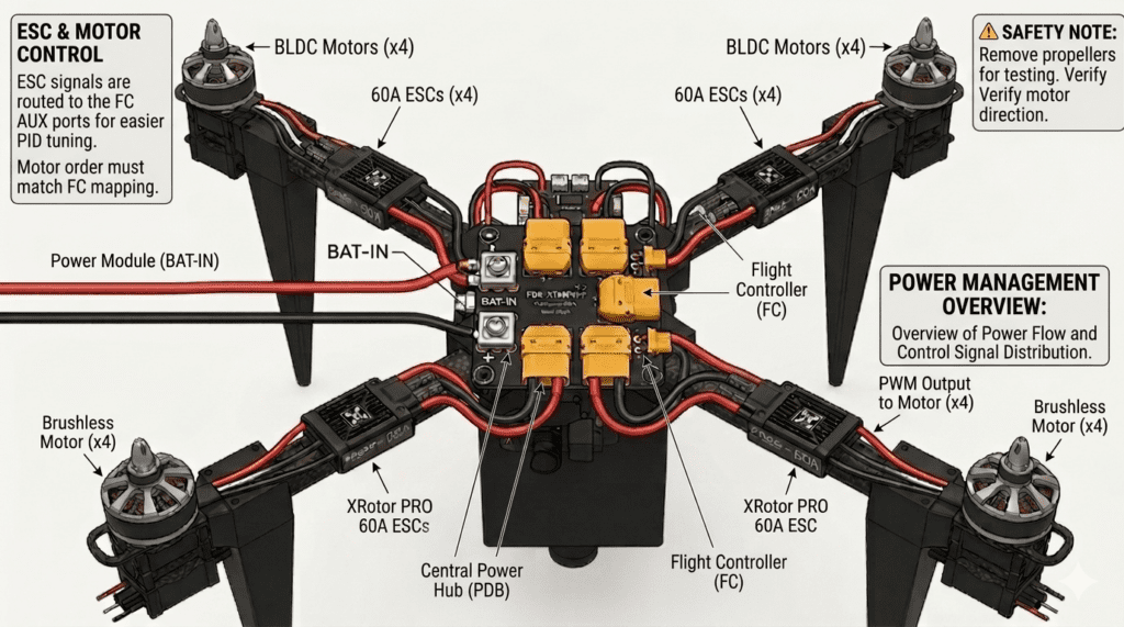
Power is supplied from the power module to the PDB, which then distributes it to each ESC (XRotor PRO 60A). Each ESC is secured to its corresponding arm mount, and the power and signal wires are routed through the arm pipe to the center of the drone. The power wires of each ESC are then connected to the XT90 terminals on the PDB.
1-2) Motor Wiring (ESC → Motor)
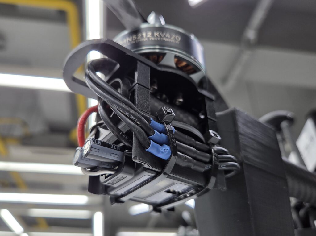
Each motor is connected to the three output cables of its corresponding ESC. Since the rotation direction of a three-phase brushless motor is determined by the order in which the three cables are connected, the direction will be verified and adjusted as necessary in the motor direction configuration step.
1-3) Signal Wire Wiring (ESC → FC)
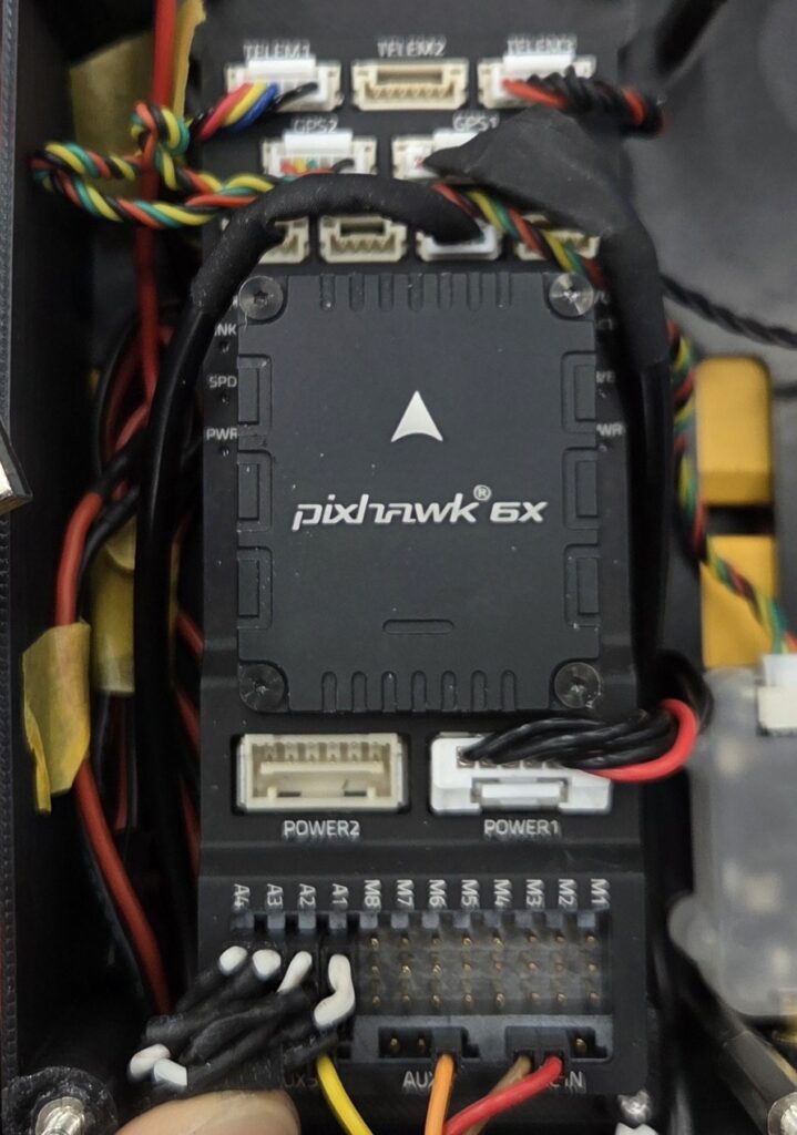
The signal wires of each ESC are connected to the AUX ports of the FC. While M1~8 ports are commonly used, the 911 FALCON uses the A1~4 ports for easier PID tuning in later stages. Each ESC’s signal wire must be connected to the FC port that corresponds to the correct motor position, as shown in the image below.
2. Motor Direction Configuration
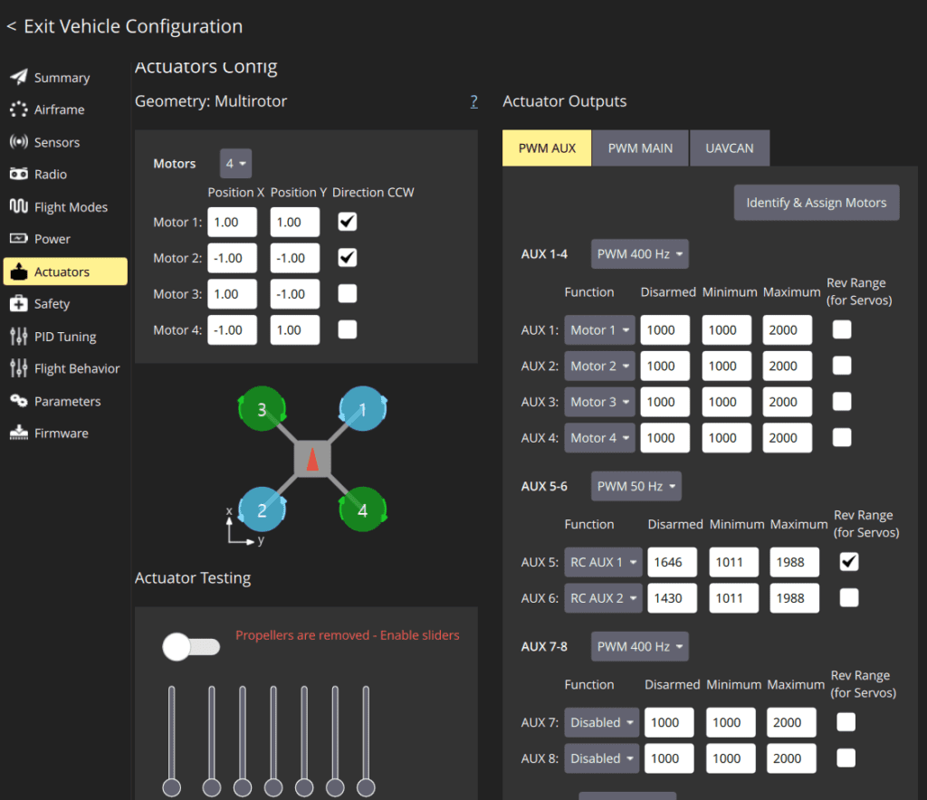
Motor direction can be configured in QGC‘s Actuator tab.
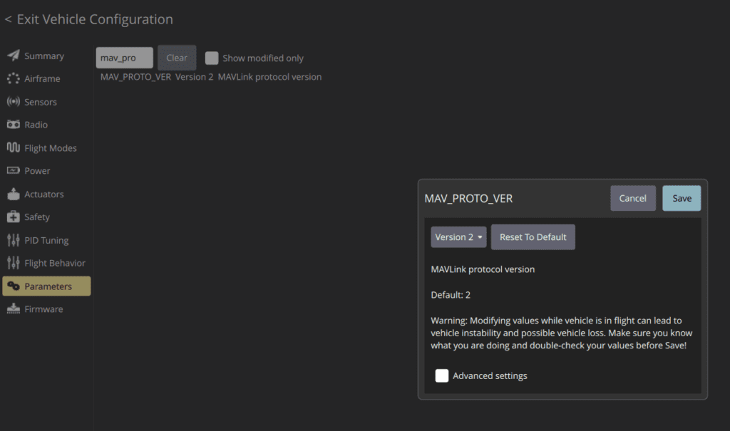
If the Actuator tab is not visible and only a Motor tab is displayed, navigate to the Parameters tab and change the MAV_PROTO_VER parameter to Version 2, then reboot the FC to activate the Actuator tab.
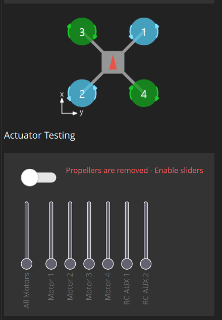
Using the motor test function at the bottom of the Actuator tab, spin each motor one at a time to verify that it rotates in the correct direction. If any motor is spinning in the wrong direction, swapping the positions of any two of the three ESC output cables will reverse its rotation direction.
⚠️ Caution: When performing motor rotation tests, always ensure that the motors are mounted to the frame and that all propellers are removed. This is a mandatory safety guideline that must be followed without exception.
3. Arming
After confirming that all four motors rotate correctly, proceed with arming via the transmitter. The transmitter and receiver must be bound as configured in the previous article. If the receiver does not connect when the transmitter is powered on, reboot the aircraft. Raising the previously assigned arming switch will arm the aircraft.
If arming does not occur, consider the following two scenarios.
(1) No arming failure beep
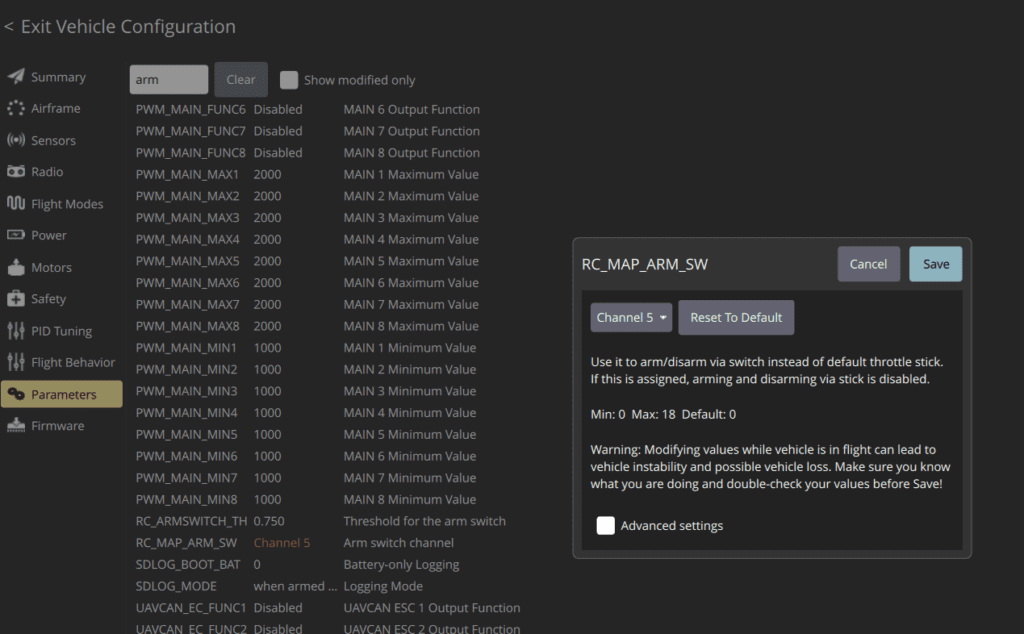
The transmitter and receiver may not be bound, or the arming switch parameter may have been assigned to the wrong channel. Check in order: Binding → Flight Mode → Parameters. For the parameter check, verify that RC_MAP_ARM_SW is correctly assigned to the intended switch channel.
(2) Beep sound (3 rapid beeps)
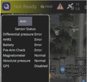
The throttle may be raised, or the aircraft may currently be in a mode that does not allow arming (e.g., Position mode in an indoor environment, Return mode). Check the throttle position and current flight mode.
Note that beep sounds are generated by the GPS module, so if the GPS has not yet been installed, no beep will sound.
4. Throttle Operation Check
After arming, verify throttle operation. If the motors do not spin fast enough even at full throttle, check the following four possible causes.
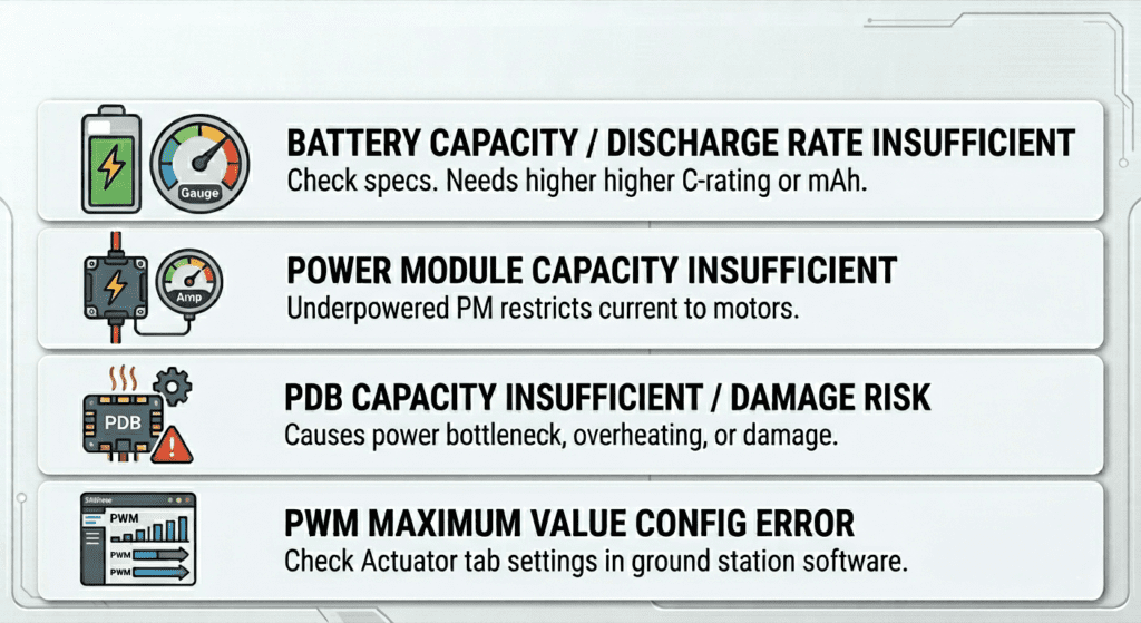
- Insufficient battery capacity or discharge rate: Check the battery specifications and capacity.
- Insufficient power module capacity: If the power module’s capacity is lower than required, the current supplied to the motors may be insufficient, resulting in inadequate throttle response.
- Insufficient PDB capacity: If the PDB’s rated capacity is lower than the total maximum current draw of all four motors, a power bottleneck may occur, causing heat buildup in the PDB and in the worst case, PDB damage and short circuit. Always use components with appropriate capacity ratings.
- PWM Maximum value set too low: The PWM Maximum value in the Actuator tab may be set too low. Check and adjust the value to an appropriate level.
This article covered the motor and ESC wiring process and arming and throttle operation verification for the 911 FALCON drone. We went through the power wiring from the power module through the PDB to the ESC, motor wiring, and signal wire connections to the FC, followed by motor direction configuration, arming, and throttle operation verification to confirm that the aircraft responds correctly to transmitter input.
In the next article, we will cover the video transmitter, OSD, and camera wiring and setup process. We will focus on the wiring between the OSD, FPV camera, and VTX, as well as the configuration process for each device. Thank you for reading.

Author: Guenchan lee, Senior Researcher of QUAD Drone Lab.
Date: May 28, 2026
![[Hybrid Navigation System Series Part 1: Overview] Flying Hundreds of Kilometers Without GPS? Learning a Hybrid Navigation System from WWII Pilots](https://quad-drone-lab.co.kr/wp-content/uploads/2026/04/컴패니언-컴퓨터-기반의-AI-지형지물-보정-768x419.jpg)
![[Everything About Drone Batteries]Part 3: The Evolution to High-Voltage Systems: The World of 6S, 8S, and 12S](https://quad-drone-lab.co.kr/wp-content/uploads/2026/05/Inside-the-Intelligence-Battery-Diagram-768x429.png)
![[PX4 Tuning Series Appendix] Racing Drone Tuning Guide (Racer Setup): Unlocking Extreme Performance](https://quad-drone-lab.co.kr/wp-content/uploads/2026/03/Racing-Drone-Minimalism-and-Balance-768x429.png)
![PX4 MAVSDK – C++ Programming [Episode 5] Querying System Information and Using Telemetry](https://quad-drone-lab.co.kr/wp-content/uploads/2026/03/0315_인포그래피-768x512.png)
![[하이브리드 항법 시스템: 제3편] 산업용 고성능 INS(관성항법장치) 이해와 GPS 교란 시뮬레이터 만들기](https://quad-drone-lab.co.kr/wp-content/uploads/2026/04/Physics-of-IMU-Drift-Errors-1-768x429.jpg)
![ROS2 Mastery [Part 2] Core Communication Concepts of ROS2 and How to Use the Powerful Utility “RQT”](https://quad-drone-lab.co.kr/wp-content/uploads/2026/03/0331_그림6-768x512.png)