

[Hybrid Navigation System: Part 2] Principles of PX4 Autonomous Navigation and Gazebo SITL Simulator Configuration
Hello! University students and drone researchers exploring the frontiers of autonomous flight and navigation technologies, welcome back to the QUAD Drone Lab.
In our previous post, <Part 1>, we drew inspiration from the wisdom of World War II fighter pilots to design a blueprint for a ‘3-Stage Non-GPS Hybrid Unmanned Navigation System’. This system allows a kamikaze drone to navigate hundreds of kilometers and strike its target precisely, even in modern battlefields where GNSS (GPS) signals are completely denied or jammed.
However, no matter how brilliant an algorithm is on paper, to successfully implement it onto an actual drone, we must first understand the fundamental ‘principles’ of how the drone’s “brain” perceives the world and navigates. Furthermore, to prevent the disaster of crashing an expensive drone during development, creating a safe ‘virtual environment (Simulator)’ for testing is absolutely essential.
In this <Part 2> of our series, we will dive deep into the autonomous navigation principles of PX4—the open-source flight control stack loved by researchers worldwide. We will also provide a friendly, step-by-step guide to setting up the Gazebo SITL (Software In The Loop) simulator and writing your first Python control code to test our algorithms safely without risking hardware damage.
Let’s dive right in!
1. The Brain of Autonomous Navigation: Principles and Mechanisms of PX4 EKF2
Just as a person walking with their eyes closed relies on their inner ear (vestibular system) to sense direction and distance, a drone must fuse various sensor data to estimate its current position and attitude. In the PX4 Flight Controller, the core module responsible for this magic is the EKF2 (Extended Kalman Filter 2).
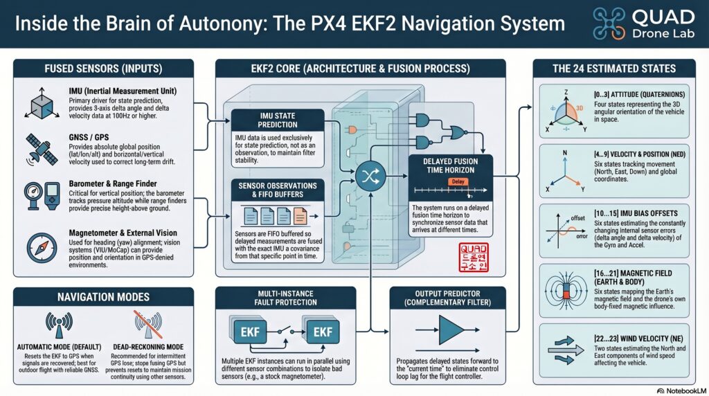
EKF2 is an advanced mathematical algorithm that takes noisy data from the Inertial Measurement Unit (IMU), magnetometer (compass), barometer, and airspeed sensor, and seamlessly fuses them to estimate the drone’s 24 states in real-time.
These 24 state variables include:
- Attitude: 4 Quaternion states (representing Roll, Pitch, Yaw)
- Velocity: 3-axis velocity in the North, East, Down (NED) frame
- Position: 3-axis position in the NED frame
- Sensor Bias: Gyroscope and Accelerometer offsets (These are the most critical factors that determine the accumulated drift during long-range dead reckoning!)
- Magnetic Field: 6 states for Earth and Body magnetic fields
- Wind Velocity: North and East wind speeds (Absolutely essential for overcoming crosswinds, just like the WWII pilots did!)
💡 The Magic of the ‘Delayed Time Horizon’
The sensors mounted on a drone process and send data to the EKF at different speeds, creating varying time delays. To handle this, EKF2 uses a ‘Delayed Time Horizon’ approach. It buffers the incoming data (FIFO) and performs the fusion math at a specific point in the past where all sensor data aligns. Then, using a complementary filter, it uses the fast IMU data to ‘propagate’ or fast-forward that past state to the ‘current time’. This allows the drone to maintain highly precise and mathematically consistent state estimation, even during highly dynamic maneuvers.
📍 Local Position vs. Global Position
- Global Position: This uses the WGS84 ellipsoid model to represent Latitude, Longitude, and Altitude (usually provided by GPS).
- Local Position: This uses a Cartesian NED (North, East, Down) coordinate system measured in meters. The point where the drone is powered on is set as the origin
(0, 0, 0).
In our ‘Non-GPS Hybrid Navigation System’, since global GPS signals are jammed or denied, the drone will rely entirely on the IMU integrations provided by EKF2 to navigate within this Local NED coordinate system.
2. The Drone’s Guide: Flight Modes, Navigator, and Offboard Mode
If EKF2 acts as the sensory system answering the question “Where am I and how am I oriented?”, the Navigator module acts as the brain’s frontal lobe, answering “Where do I go next?” by generating a flight trajectory. PX4 offers several flight modes to dictate how the Navigator behaves:
- Hold Mode: The drone hovers in place, maintaining its current position and altitude.
- Mission Mode: The drone autonomously follows a pre-programmed set of GPS waypoints uploaded via QGroundControl.
- Offboard Mode: ⭐️ This is the most important mode for our research! ⭐️
🚀 Why Offboard Mode?
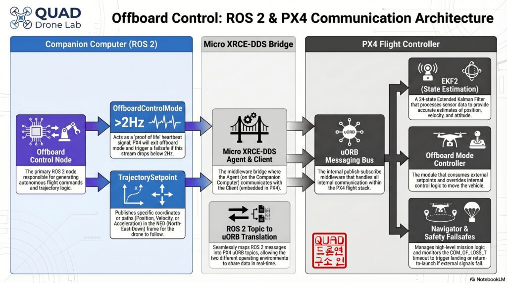
In a GPS-denied environment, standard Mission Mode cannot function. Therefore, we must mount a Companion Computer (like a Raspberry Pi or NVIDIA Jetson Nano) running ROS 2 (Robot Operating System 2) to process heavy computer vision and deep learning algorithms on board.
Offboard mode ignores the internal PX4 Navigator’s planned missions. Instead, it allows our external ROS 2 Companion Computer to directly stream real-time setpoints, commanding the drone with instructions like “Fly to local X, Y, Z coordinates!” or “Fly at this specific velocity vector!”
⚠️ The Failsafe Mechanism of Offboard Mode
Handing over complete control of a flying blender to an external computer can be dangerous. What if the ROS 2 script crashes or freezes? To prevent a catastrophic fall, PX4 requires a ‘Proof of Life’ (Heartbeat). The ROS 2 node must continuously publish an OffboardControlMode message at a minimum rate of 2Hz (twice per second). If PX4 stops receiving this heartbeat, it immediately terminates Offboard mode and enters a failsafe state (such as landing or loitering), which is determined by the COM_OBL_RC_ACT parameter.
3. A Safe Laboratory: Gazebo SITL Simulator Setup
Testing unproven code on a real drone outdoors often leads to crashes, costing thousands of dollars in hardware. For researchers, a physics-engine-based simulator that behaves exactly like the real drone is essential. This is where SITL (Software In The Loop) comes in.
Assuming you have an Ubuntu 22.04 and ROS 2 Humble environment ready, let’s set up our virtual lab.
1. Clone and Build the PX4 Source Code First, download the PX4 Autopilot repository and install the necessary dependencies:
git clone https://github.com/PX4/PX4-Autopilot.git --recursive
cd PX4-Autopilot/
bash ./Tools/setup/ubuntu.sh
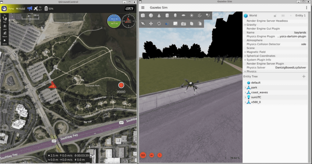
2. Launch the Gazebo Simulator With a single command, you can spawn a virtual quadcopter (x500) inside a 3D simulated world:
make px4_sitl gz_x500
Once the command is executed, the Gazebo window will open with your drone. If you open QGroundControl (QGC) on the same computer, it will automatically connect to the simulated drone just as if it were plugged in via USB, allowing you to monitor all its telemetry data.
3. Start the Micro XRCE-DDS Agent For PX4 (which uses its internal uORB messaging) to communicate with ROS 2 (which uses DDS), we need a bridge. Open a new terminal and run the Agent:
MicroXRCEAgent udp4 -p 8888
Now, your virtual drone is fully prepared to communicate with your custom Python code!
4. [Hands-on] A Taste of Offboard Control with Python and ROS 2
To wrap up, let’s write a simple ROS 2 Python node that switches the virtual drone into Offboard mode, arms the motors, and commands it to take off to an altitude of 5 meters. (We’ve designed this Python code to be highly intuitive for the ROS 2 ecosystem).
import rclpy
from rclpy.node import Node
from rclpy.qos import QoSProfile, ReliabilityPolicy, HistoryPolicy

# Import necessary PX4 messages
from px4_msgs.msg import OffboardControlMode, TrajectorySetpoint, VehicleCommand

class OffboardControlNode(Node):
    def __init__(self):
        super().__init__('offboard_control_node')

        # Configure QoS profile for reliable communication
        qos_profile = QoSProfile(
            reliability=ReliabilityPolicy.BEST_EFFORT,
            history=HistoryPolicy.KEEP_LAST,
            depth=1
        )

        # Create Publishers
        self.offboard_ctrl_mode_pub = self.create_publisher(OffboardControlMode, '/fmu/in/offboard_control_mode', qos_profile)
        self.trajectory_setpoint_pub = self.create_publisher(TrajectorySetpoint, '/fmu/in/trajectory_setpoint', qos_profile)
        self.vehicle_cmd_pub = self.create_publisher(VehicleCommand, '/fmu/in/vehicle_command', qos_profile)

        # Set a timer to run at 10Hz (100ms) to satisfy the PX4 >2Hz heartbeat requirement
        self.timer = self.create_timer(0.1, self.timer_callback)
        self.setpoint_counter = 0

    def timer_callback(self):
        # 1. Publish the Heartbeat and declare we will use Position Control
        mode_msg = OffboardControlMode()
        mode_msg.position = True       # Enable Position Control
        mode_msg.velocity = False
        mode_msg.acceleration = False
        mode_msg.attitude = False
        mode_msg.body_rate = False
        mode_msg.timestamp = int(self.get_clock().now().nanoseconds / 1000)
        self.offboard_ctrl_mode_pub.publish(mode_msg)

        # 2. Publish the Target Position (Setpoint) in Local NED coordinates
        # x (North) = 0.0m, y (East) = 0.0m, z (Down) = -5.0m (Climb to 5m altitude)
        sp_msg = TrajectorySetpoint()
        sp_msg.position = [0.0, 0.0, -5.0]
        sp_msg.yaw = 0.0
        sp_msg.timestamp = int(self.get_clock().now().nanoseconds / 1000)
        self.trajectory_setpoint_pub.publish(sp_msg)

        # 3. For safety, send setpoints for 1 second (10 iterations) before arming and switching modes
        if self.setpoint_counter == 10:
            self.publish_vehicle_command(VehicleCommand.VEHICLE_CMD_DO_SET_MODE, 1.0, 6.0) # Switch to Offboard Mode
            self.publish_vehicle_command(VehicleCommand.VEHICLE_CMD_COMPONENT_ARM_DISARM, 1.0) # Arm the motors
            self.get_logger().info('Offboard mode activated & Motors armed! Taking off to 5m.')

        if self.setpoint_counter < 11:
            self.setpoint_counter += 1

    def publish_vehicle_command(self, command, param1=0.0, param2=0.0):
        # Helper function to send VehicleCommands to PX4
        cmd_msg = VehicleCommand()
        cmd_msg.command = command
        cmd_msg.param1 = param1
        cmd_msg.param2 = param2
        cmd_msg.target_system = 1
        cmd_msg.target_component = 1
        cmd_msg.source_system = 1
        cmd_msg.source_component = 1
        cmd_msg.from_external = True
        cmd_msg.timestamp = int(self.get_clock().now().nanoseconds / 1000)
        self.vehicle_cmd_pub.publish(cmd_msg)

def main(args=None):
    rclpy.init(args=args)
    offboard_control_node = OffboardControlNode()
    rclpy.spin(offboard_control_node)
    offboard_control_node.destroy_node()
    rclpy.shutdown()

if __name__ == '__main__':
    main()
If you run this code (ros2 run <package_name> <node_name>) alongside your running Gazebo simulator, you will see the virtual drone arm its motors and gracefully take off to hover precisely at a 5-meter altitude (z = -5.0 in the NED frame). Congratulations! You have successfully mastered the basics of ROS 2 Offboard control!
Wrapping Up
In this second part of our series, we unravelled the mysteries of the drone’s brain—understanding how the PX4 EKF2 estimates state, the crucial difference between global and local coordinate systems, and the failsafe mechanics of Offboard Mode where an external companion computer takes the wheel. We also built our very own Gazebo SITL simulation environment and completed a hands-on Python control exercise.
With this foundation, the groundwork for implementing Dead Reckoning in a GPS-denied environment is complete. In our next post, <Part 3>, we will explore the inherent limitations of low-cost sensors when flying long distances, and dive deep into the fascinating hardware world of Industrial High-Performance INS (Inertial Navigation Systems) technology designed to overcome these very challenges.
Stay tuned for the next installment from the QUAD Drone Lab!

Author: maponarooo, CEO of QUAD Drone Lab
Date: April 13, 2026
![[Series Announcement] ROS2 Mastery: A Comprehensive ROS2 Guide for Students and Researchers](https://quad-drone-lab.co.kr/wp-content/uploads/2026/03/image-11-768x429.png)
![[New Blog Series Introduction] Everything About Drone Batteries – From Basics to Next-Generation Technologies](https://quad-drone-lab.co.kr/wp-content/uploads/2026/04/Drone-Battery-Technology-Masterclass-768x1376.jpg)
![PX4 MAVSDK – C++ Programming [5편] 시스템 정보 쿼리 및 원격 측정(Telemetry) 활용](https://quad-drone-lab.co.kr/wp-content/uploads/2026/03/0315_인포그래피-768x512.png)