
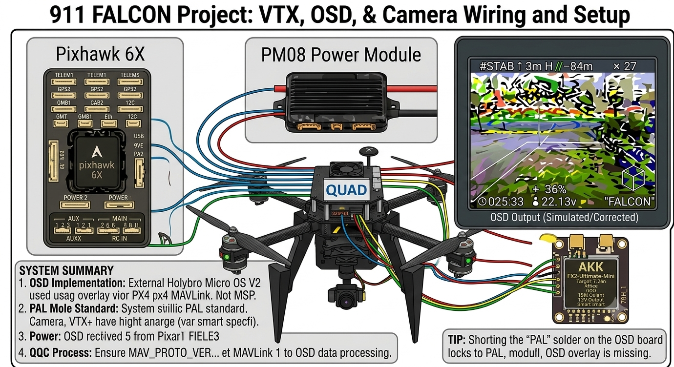
Video Transmitter, OSD, and Camera Wiring & Setup : 911 FALCON Project
Hello, this is QUAD Drone Laboratory.
I’m Geunchan Lee, Senior Researcher at QUAD Drone Lab.
In the previous article, we covered the motor and ESC wiring process and arming and throttle operation verification for the 911 FALCON drone. We went through the power wiring from the power module through the PDB to the ESC, motor wiring, and signal wire connections to the FC, followed by motor direction configuration, arming, and throttle operation verification to confirm that the aircraft responds correctly to transmitter input.
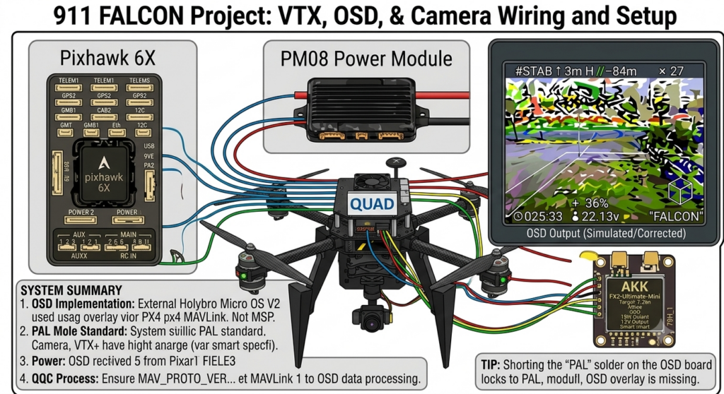
In this article, we will cover the video transmitter, OSD, and camera wiring and setup process. We will go through the wiring configuration, QGC parameter settings, OSD Configurator setup, and troubleshooting in order.
1. OSD System Overview
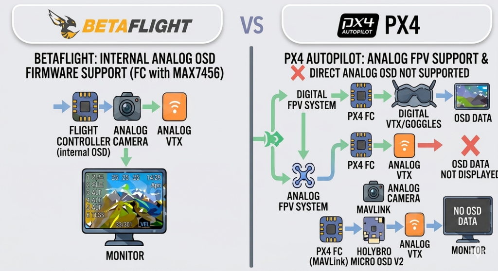
The OSD implementation method for a drone varies significantly depending on the firmware. Betaflight-based FCs have OSD functionality built directly into the firmware, allowing flight data to be overlaid onto the video feed without any external module.
PX4 firmware, on the other hand, does not process OSD internally. Instead, it implements OSD through communication with external devices. The OSD method supported by PX4 is MSP (MultiWii Serial Protocol) based, which is designed specifically for digital FPV systems such as DJI and Walksnail. In digital systems, the air unit receives MSP data and renders it directly onto the video feed, so no separate analog OSD module is required.
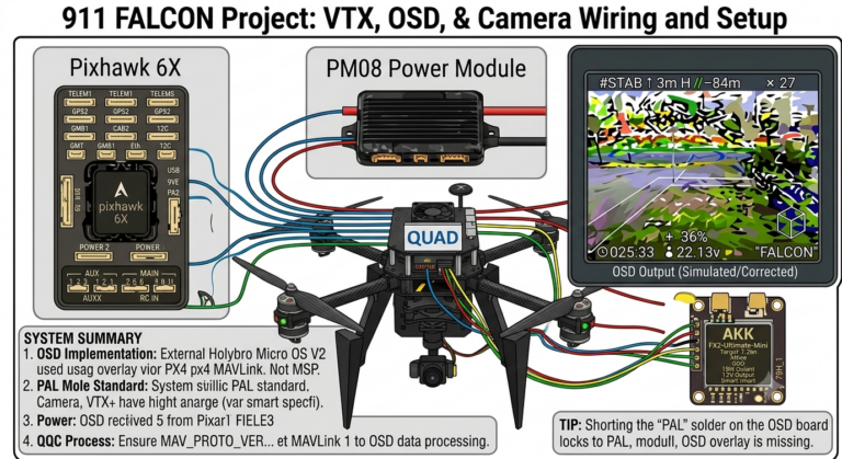
However, the 911 FALCON system uses an analog FPV camera and VTX, making the MSP approach inapplicable. To overlay flight data onto an analog video signal, a dedicated OSD module is needed — one that receives flight data from the FC via MAVLink protocol and composites it directly onto the video. For this reason, the Holybro Micro OSD V2 was used to implement OSD on the analog video feed.
2. Wiring
2-1) OSD Wiring
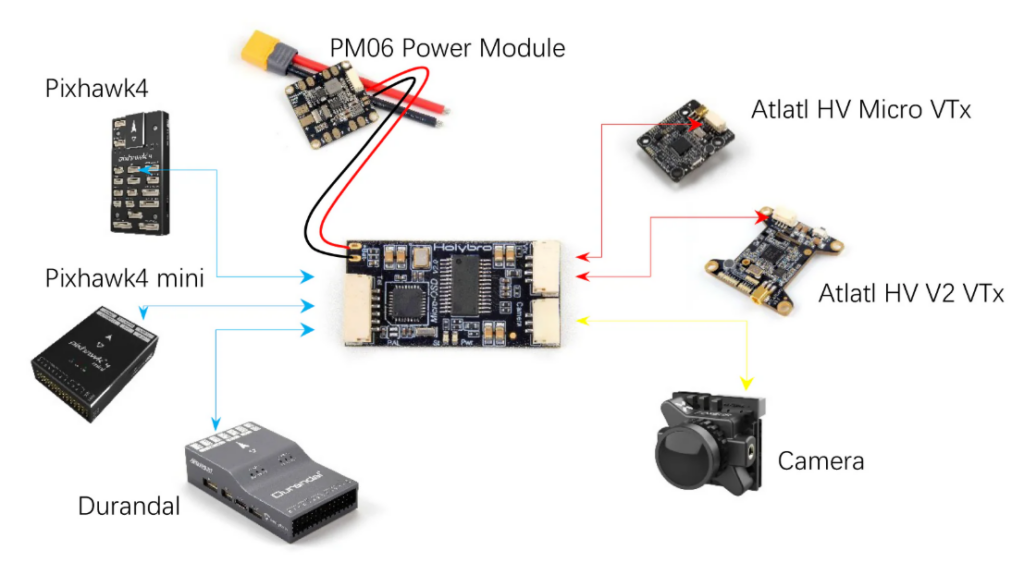
The TELEM port of the Holybro Micro OSD V2 is connected to the FC’s TELEM3 port. Following the characteristics of UART communication, the OSD’s RXD is connected to the FC’s TX, and the OSD’s TXD is connected to the FC’s RX in a cross-connection. 5V and GND are connected in the correct polarity, and the OSD module is powered by the 5V supplied through this TELEM cable.
Power for the FPV camera and VTX is supplied through the BAT+ / BAT- pads on the OSD board, which means battery voltage is applied directly. It is therefore essential to verify that the camera and VTX support the full battery voltage before powering the system.
2-2) FPV Camera Wiring
The video signal line of the FPV camera (Foxeer Razer Mini) is connected to the VIDEO IN of the Camera Port on the OSD board. The video captured by the camera passes through the OSD, where flight data is overlaid, before being output to the VTX.
2-3) VTX Wiring
The VTX (AKK FX2-Ultimate-Mini) is connected to the VIDEO OUT of the VTx Port on the OSD board. The video signal with OSD overlay is then wirelessly transmitted via the VTX.
QGC Parameter Settings
After completing the wiring, set the following parameters in QGroundControl (QGC)‘s Parameters tab.
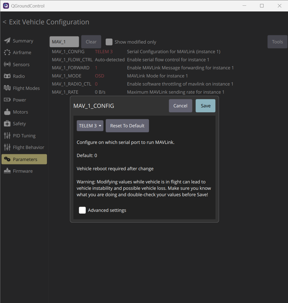
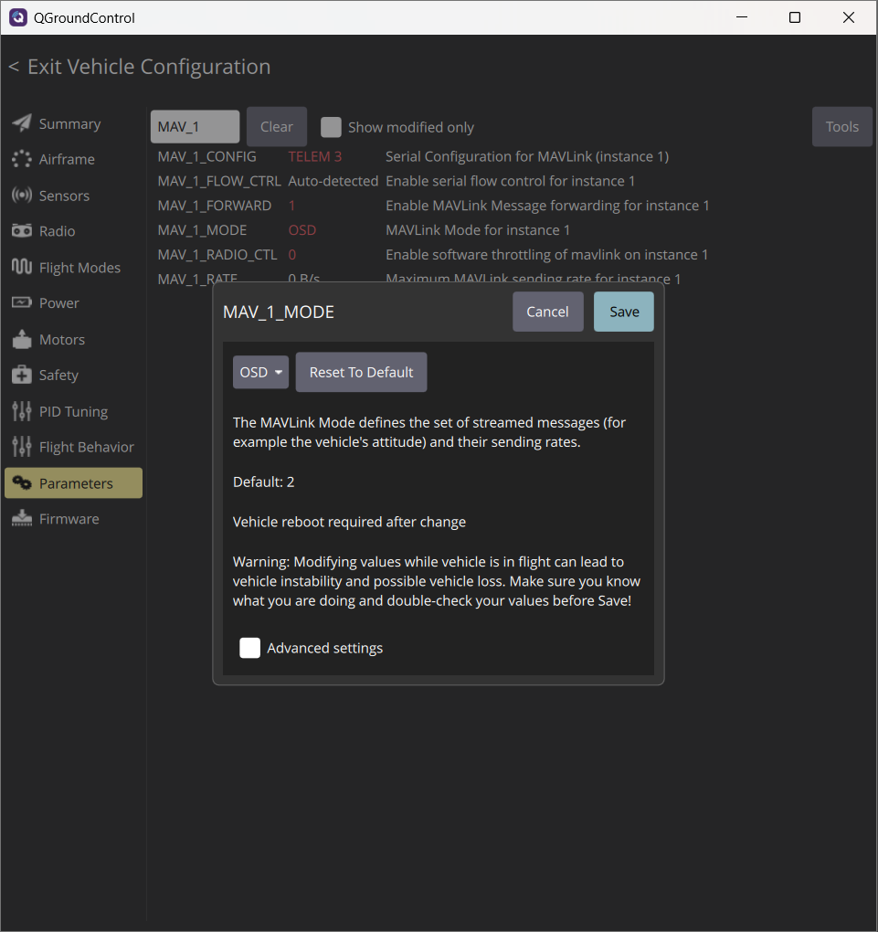
- MAV_1_CONFIG → TELEM3, designates the OSD-connected port as the MAVLink output port
- MAV_1_MODE → Onboard, sets MAVLink mode for external devices
- MAV_1_RATE → Keep default value
- SER_TEL3_BAUD → 57600, set to match the communication speed of the Holybro Micro OSD V2
- MAV_PROTO_VER → MAVLink 1
Particular attention should be paid to the MAV_PROTO_VER setting. If this value is set to MAVLink 2, the OSD will not be able to recognize the FC’s data packets, and no data will be displayed on the OSD screen. After changing any parameters, the FC must be rebooted for the settings to take effect.
4. OSD Configurator Setup
4-1) FTDI Connection
A FTDI to UART Converter (USB-C type) is used to connect the OSD module to the laptop. Connect the FTDI adapter to the OSD board’s TELEM port with the following cross-connections.
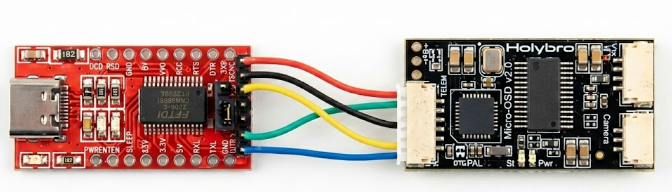
- FTDI 5V → OSD 5V
- FTDI GND → OSD GND
- FTDI TXD → OSD RXD
- FTDI RXD → OSD TXD
- FTDI DTR → OSD DTR
No battery connection is required — the OSD board is powered by the USB power from the FTDI adapter. When the connection is established correctly, the amber LED on the OSD board will begin flickering.
4-2) OSD Configurator Settings
Run OSD_Config.exe on the laptop, select the COM port corresponding to the FTDI adapter from the dropdown menu at the bottom, and click ‘Read from OSD’. Once the current settings are loaded from the OSD board, you can modify them through each tab.
(1) Config Tab

The Config tab allows you to set units, warning levels, and the transmitter channel used to toggle between two OSD screens. If you do not plan to use two separate OSD screens, it is recommended to disable the toggle feature. The Video Mode (PAL/NTSC) can also be configured in this tab.
(2) Layout Tab
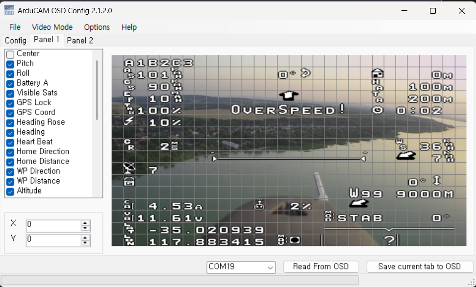
The Layout tab allows you to select which elements are displayed on the OSD and adjust their positions on screen. Select the desired element from the list on the left and drag it to the preferred position on screen. Two separate OSD layouts can be configured, and they can be switched using the channel set in the Config tab.
After completing the settings in each tab, be sure to click ‘Save Current Tab to OSD’ in the bottom right corner to save your changes.
5. OSD Not Appearing on Screen
If the OSD does not appear on the FPV screen even after completing all parameter settings and OSD Configurator setup, check the Video Mode setting.
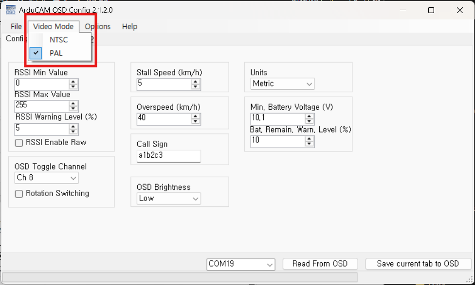
If the Video Mode in the OSD Configurator does not match the video standard of the camera and monitor, the OSD will not be displayed. In the 911 FALCON setup, the OSD began displaying correctly after changing from NTSC to PAL.
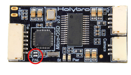
In addition to the software setting, the Holybro Micro OSD V2 board has dedicated PAL solder pads. By shorting the two pads with solder, the board can be hardware-locked to PAL mode regardless of the software setting. This is a useful method when applying PAL mode without an FTDI adapter.
💡 PAL vs NTSC: PAL uses 25 frames per second (standard in Europe and Korea), while NTSC uses 30 frames per second (standard in the US and Japan). The video standard must match between the camera and the monitor/goggles for the OSD to display correctly.
This article covered the video transmitter, OSD, and camera wiring and setup process for the 911 FALCON drone. Due to PX4 firmware’s lack of native analog OSD support, the Holybro Micro OSD V2 module was used, and the process was carried out in order from wiring to QGC parameter settings and OSD Configurator setup.
In the next article, we will cover the design of a search camera gimbal using MG90 servo motors and the implementation of head tracking. We will go through the gimbal structure design, servo motor connections, and the process of implementing head tracking, where the camera angle is synchronized with the pilot’s head movements. Thank you for reading.
YouTube Demo

Author: Guenchan lee, Senior Researcher of QUAD Drone Lab.
Date: June 19, 2026
![PX4 MAVSDK – C++ Programming [Episode 6] Basic Flight Control using Action API](https://quad-drone-lab.co.kr/wp-content/uploads/2026/03/0316_인포그래피-768x512.png)
![[ROS2 Mastery Part 7] ROS2 Service Programming – Guide to Automatic Turtle Pen Color Change Service](https://quad-drone-lab.co.kr/wp-content/uploads/2026/05/0530_인포그래픽-768x429.jpg)
![PX4 MAVSDK – C++ Programming [Part 2] Core C++ Syntax for MAVSDK](https://quad-drone-lab.co.kr/wp-content/uploads/2026/03/0312_인포그래픽-768x768.jpg)