
Drone Electrical System : 911 FALCON Project
Hello, this is QUAD Drone Laboratory.
I’m Geunchan Lee, Senior Researcher at QUAD Drone Lab.
In the previous article, we covered the battery housing design process for the 911 FALCON drone. From XT90 contact design and bolting structure to the locking system, ideal diode, and ventilation holes, all elements required for hot-swap operation were incorporated into the housing design at this stage. The entire housing structure was designed so that a single slide-in motion automatically engages the power contacts, locks the battery in place via the locking system, and enables heat dissipation all at once.
Starting from this article, we will be covering the drone setup process in detail. The setup involves multiple stages including motor wiring, receiver configuration, video system, and Jetson Nano connection. Before diving into each stage, we will first organize the electrical system that forms the foundation of the entire setup.
In this article, we will go through the overall power supply flow — from the battery to each component — and explain how power is distributed throughout the system.

Drone Electrical System Overview
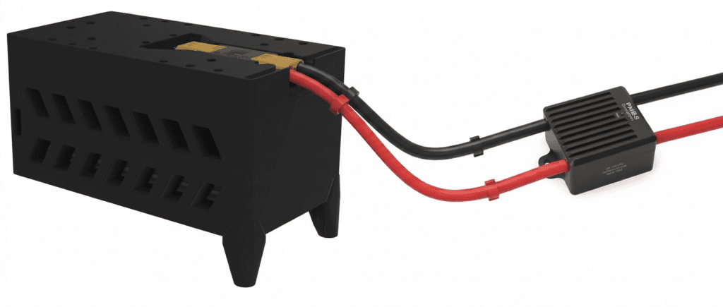
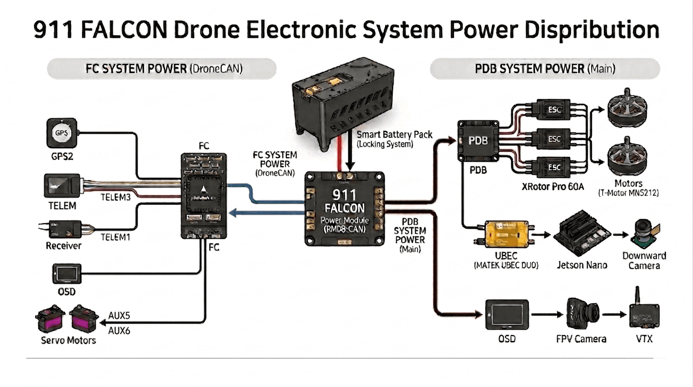
The drone’s electrical system consists of a power circuit, in which power output from the battery is distributed to each component via the power module, and a signal circuit, in which peripheral devices are connected through the FC. The 911 FALCON follows this same structure, with the electrical system beginning as battery power is fed into the power module (PM08-CAN).
From the power module, power splits into two branches that supply the entire system: the FC circuit and the PDB circuit.
- FC circuit: Power and DroneCAN communication are connected to the FC via the 6-pin connector on the side of the power module.
- PDB circuit: Power is supplied to the PDB via the main power line of the power module, and distributed to each component from there.
Below, we will go through the wiring of each device in order, divided into the FC circuit and the PDB circuit.
1. FC Circuit
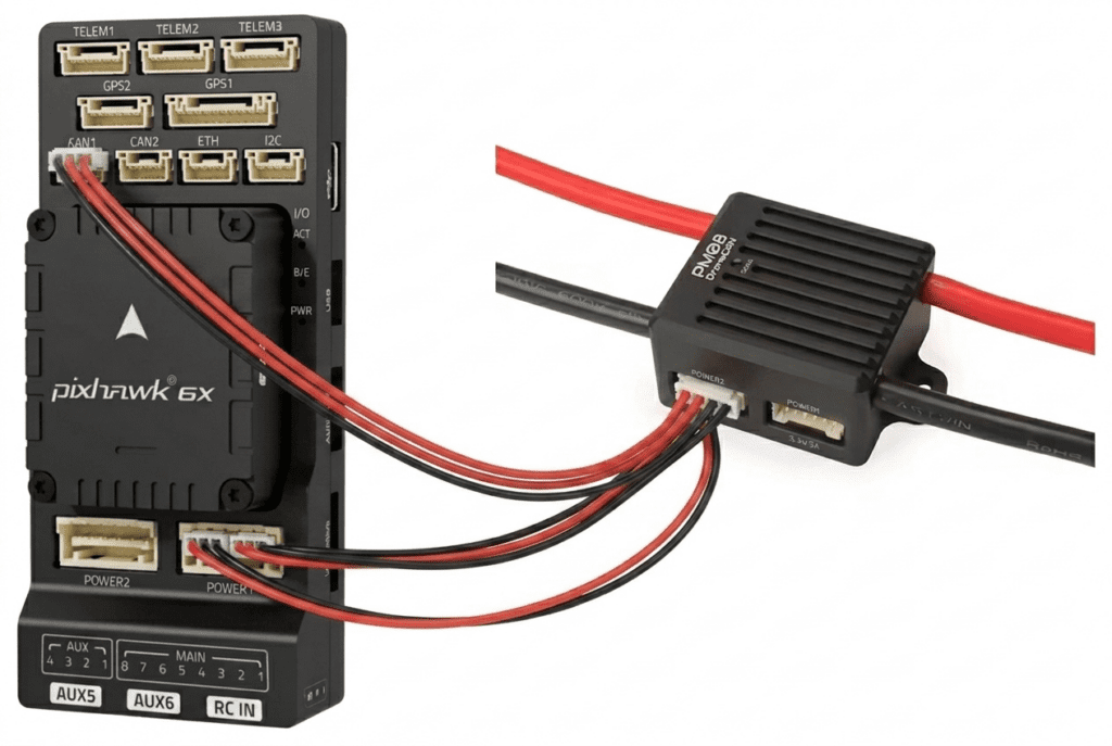
The cable from the 6-pin connector on the side of the power module contains both power lines and CAN communication lines. Typically, the FC’s power port is designed around I2C-based power modules, meaning that a power module supporting I2C can confirm battery status without additional wiring. However, since the PM08-CAN only supports DroneCAN communication, the power line and CAN communication line were separated from the 6-pin cable and wired individually to the FC’s power port and CAN port.
1-1. FC

The FC (Pixhawk 6X) supplies power and signals to a variety of peripheral devices. Each device is connected to its designated port on the FC.
(1) GPS

The GPS measures the drone’s position, altitude, and speed in real time and transmits this data to the FC. It is connected to the gps1 port, and the FC uses this data to perform autonomous flight and position hold functions.
(2) Telemetry

The telemetry module handles wireless data communication between the drone and the ground station. Connected to the gps2 port, it transmits flight status, battery level, and GPS coordinates to the ground station in real time.
(3) Receiver

The receiver captures the pilot’s transmitter input signals and forwards them to the FC. Connected to the telem1 port, the FC uses these signals to control motor output and aircraft attitude.
(4) OSD

The OSD receives flight data from the FC and overlays it onto the FPV video feed. Connected to the telem3 port, it displays real-time information such as battery voltage, airspeed, and altitude on the video feed. Power for OSD operation is also supplied through this port along with the flight data.
(5) Servo Motor
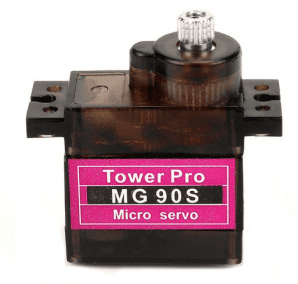
The servo motor is used for gimbal control to adjust the camera angle. Connected to aux ports 5 and 6, it drives the gimbal’s tilt and roll axes based on transmitter input.
2. PDB Circuit
The main power line from the power module connects to the PDB. While the power module and PDB were originally designed to be connected via an XT90 connector, limited space inside the airframe required the connector to be removed and the wires to be directly soldered. Power is then distributed from the PDB to each component.
2-1. ESC

Power is supplied from the PDB to each ESC (XRotor PRO 60A) via XT90 connectors. The ESC’s signal wires are connected to the FC’s aux ports 1, 2, 3, and 4, receiving motor control signals from the FC.
(1) Motor

Each motor receives power from its corresponding ESC and drives the motor (T-Motor MN5212). The ESC applies battery voltage directly to the motor and controls its RPM based on the FC’s control signals.
2-2. OSD
Power is supplied from the PDB to the OSD (Holybro Micro OSD V2). This power is not used for the OSD’s own operation — rather, it serves as a power distribution path for the FPV camera and VTX.
(1) FPV Camera

The FPV camera receives power through the OSD, and the camera video signal is passed through the OSD to the VTX.
(2) VTX

The VTX receives both power and video signal from the OSD and transmits the video wirelessly.
2-3. UBEC
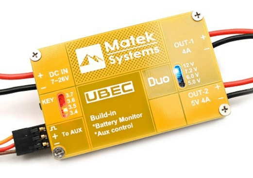
Power is supplied from the PDB to the UBEC (MATEK UBEC DUO). The UBEC steps down the battery voltage to 12V and supplies stable power to the Jetson Nano.
(1) Jetson Nano
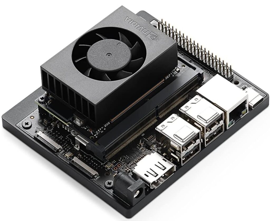
Receives 12V power from the UBEC via a barrel jack.
(2) Downward Camera
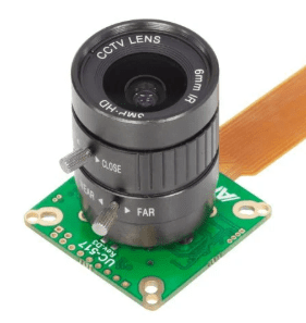
Connected to the Jetson Nano via a CSI cable, used to identify the landing target during precision landing.
Electrical System Structure Summary
Below is a summary of the overall power supply structure of the 911 FALCON drone’s electrical system.
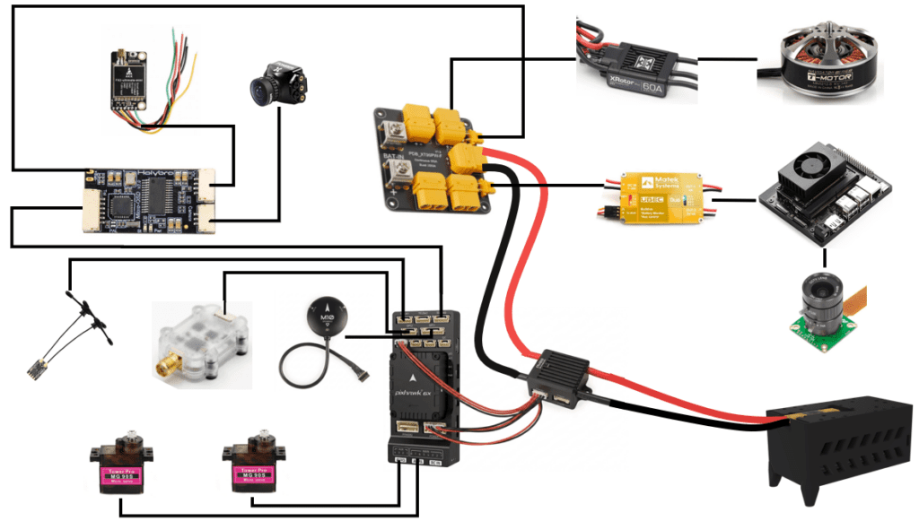
Starting from the battery, power flows through the power module and splits into the FC circuit and PDB circuit, supplying each component in the system.
This article covered the overall power supply flow of the 911 FALCON drone’s electrical system. We confirmed the structure in which power is supplied to each component, divided into the FC circuit and PDB circuit based on the power module.
In the next article, we will cover the receiver wiring and setup process based on the electrical system organized in this article. We will go through the process in order — from transmitter channel configuration and ELRS version verification, to receiver wiring, firmware update, and binding, and finally FC parameter settings, RC calibration, and flight mode configuration. Thank you for reading.

Author: Guenchan lee, Senior Researcher of QUAD Drone Lab.
Date: May 06, 2026
![[Everything About Drone Batteries] Part 1: Drone Battery Fundamentals and Chemical Characteristics: LiPo vs. Li-Ion](https://quad-drone-lab.co.kr/wp-content/uploads/2026/04/Drone-Battery-Anatomy-and-Assembly-768x429.jpg)
![ROS2 Mastery [Part 2] Core Communication Concepts of ROS2 and How to Use the Powerful Utility “RQT”](https://quad-drone-lab.co.kr/wp-content/uploads/2026/03/0331_그림6-768x512.png)
![PX4 MAVSDK – C++ Programming [Episode 11] Complete Comparison of MAVSDK vs MAVROS vs uXRCE-DDS](https://quad-drone-lab.co.kr/wp-content/uploads/2026/03/0322_인포그래피-768x512.png)
![[하이브리드 항법 시스템: 제5편] [구현-1단계] 순항 단계: 고전적 추측 항법, 풍향 추정, 그리고 Gazebo 바람 시뮬레이션 구현](https://quad-drone-lab.co.kr/wp-content/uploads/2026/05/Drone-Vector-Navigation-Crab-Angle-768x429.png)