
[ROS2 Mastery Part 9] Static Frame and Moving Robot TF2 Broadcasting Practice Guide
Hello, everyone! Welcome, undergraduate students and researchers who are deeply exploring the world of autonomous driving and robot system control. A sincere welcome to Part 9 of the ‘ROS2 Accelerated Mastery Course’ blog series, brought to you based on materials from the QUAD Drone Research Lab.
In our previous Part 8, we theoretically learned about the basic concepts and tree structure of TF2 (Transform System), which is the core of robot mathematics and elegantly solves complex 3D spatial calculations.
Now, it is time to get our hands dirty based on that theory! In this Part 9, before writing Python code, we will practice the entire process of broadcasting a ‘Static Frame’ into the system and visualizing the transform tree of a ‘Moving (Dynamic) Robot’ defined by URDF, all by utilizing the powerful command-line tools and utility nodes provided by default in ROS2.
In particular, we will cover in detail how to use key debugging tools that can analyze causes when numerous frames get tangled up during the research process, so please stay focused and follow along until the end!
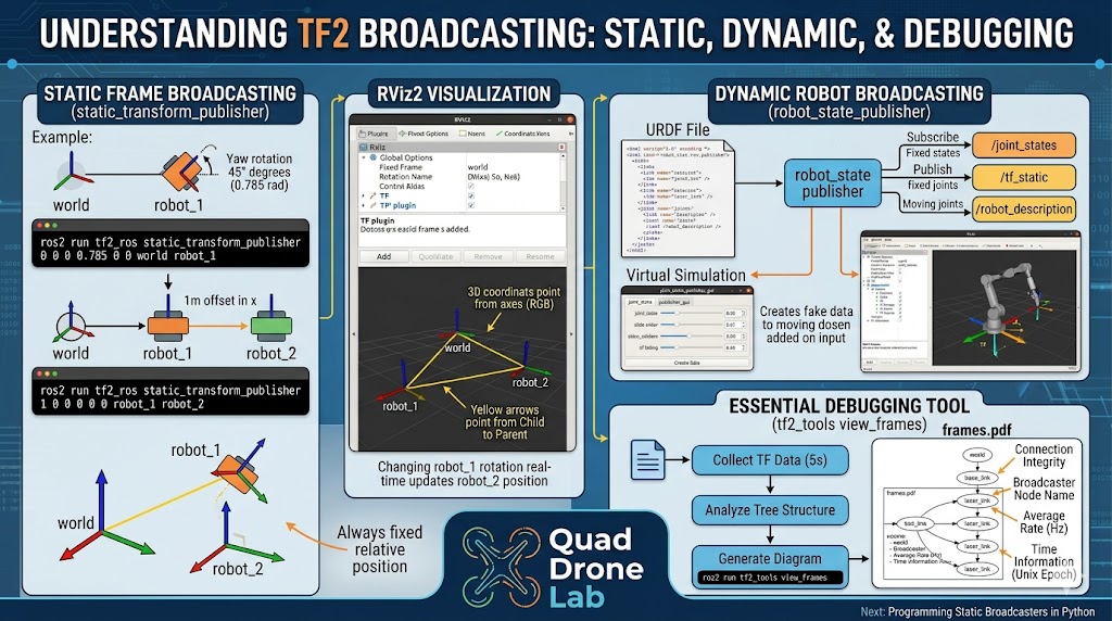
The Wizard of Static Transforms: static_transform_publisher Hands-on Guide
When building a robot system, you often need to define the position of sensors (e.g., LiDAR, fixed cameras) that are fixed to a reference point in a room (world) or to the robot’s body (base_link) and never move. A relationship between frames that does not change over time like this is called a ‘Static Transform.’
ROS2 provides a tool called static_transform_publisher that allows you to immediately publish these static transforms to the network with a single line of terminal command. This tool is a highly useful utility that acts as a “glue” to align coordinate systems between different nodes in an actual development environment.
1. Single Frame Broadcasting Command Structure
The basic command structure used in the terminal is as follows. Input the translation and rotation values in order.
- Structure:
ros2 run tf2_ros static_transform_publisher [x] [y] [z] [yaw] [pitch] [roll] [parent_frame] [child_frame] - Precautions: The rotation angles (yaw, pitch, roll) are in radians, not degrees, and are processed in the order converted based on the local coordinate system.
2. Creating Two Robot Frames
Let’s construct a transform tree by entering actual commands. Open a first terminal, and we will create a robot_1 frame starting from the top-most parent world frame. The robot_1 frame is located at the origin (0, 0, 0) but is set to be rotated by 45 degrees (approximately 0.785 radians) around the Z-axis.
First Terminal: world -> robot_1 (45-degree rotation)
ros2 run tf2_ros static_transform_publisher 0 0 0 0.785 0 0 world robot_1
Now, let’s assume a second robot (robot_2) that always follows the first robot like a sidecar, staying 1m away to its right (in the x-axis direction). Open a new terminal and enter the command below.
Second Terminal: robot_1 -> robot_2 (Move 1m along the x-axis)
ros2 run tf2_ros static_transform_publisher 1 0 0 0 0 0 robot_1 robot_2
Once these commands are executed, the coordinate transform information we defined begins to be broadcasted across the entire system in the background through the /tf_static topic.
3D Transform Tree Visualization Using RViz2
There is a limit to just imagining the structure of invisible coordinate systems in your head. Let’s verify how the frames we just launched are arranged in space through RViz2, the powerful 3D visualization tool of ROS2.
Open a third terminal and execute the command.
rviz2
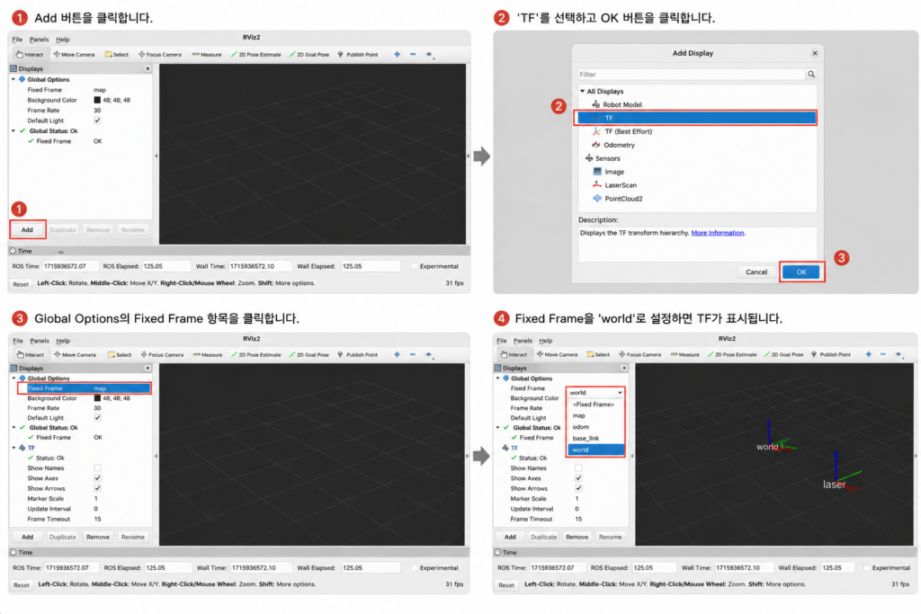
1. RViz2 Configuration Guide
- Add Plugin: When RViz first runs, a blank screen will appear. Click the [Add] button at the bottom left, select [TF] from the list, and add it.
- Set Fixed Frame: Nothing might appear on the screen yet, or an error might pop up. You need to tell RViz, “Which frame should be used as the reference (ground) to render the screen?” In the “Global Options” at the top of the left panel, change the “Fixed Frame” value from
maptoworld, which is the top-most frame we just created. - Verify Visualization: As the “Global Status” changes to OK, three coordinate system axes (
world,robot_1,robot_2) and yellow lines connecting them will appear in the center of the screen.
[Researcher Observation Point] If you look closely at the RViz screen, you will notice that the yellow arrows connecting each frame do not point from parent (world) to child (robot_1), but rather from the child frame toward the parent frame. This visually reflects the mathematical structure where the transform matrix calculates and maps the child’s local coordinates up to the parent’s reference coordinates.
Go back to the first terminal, terminate the running process (Ctrl+C), and try running it again after changing the rotation angle to 90 degrees (1.57 radians).
ros2 run tf2_ros static_transform_publisher 0 0 0 1.57 0 0 world robot_1
As robot_1 rotates by 90 degrees, you can see in real time that its dependent child frame, robot_2, also moves along a trajectory following the X-axis direction of robot_1. This is exactly the power of the TF2 tree structure!
Broadcasting a Moving Robot: Combining URDF and TF2
Beyond simple static frames, how do we handle the transforms of a robotic arm with moving joints or a driving mobile robot? Since robots do not stay still and continuously move, dynamic transforms are essential.
1. The Role of the Robot Modeling File (URDF)
defined in an XML-formatted URDF (Universal Robot Description Format) file. Inside a URDF file, rigid parts called ‘Links’ are bound together through a parent-child tree structure via ‘Joints.’ As researchers, you might have already noticed: the Link/Joint structure of URDF matches perfectly with the Frame/Transform structure of TF2 on a 1:1 basis!
2. The Magic of robot_state_publisher
Thanks to this similarity, we do not need to code the transforms by manually calculating the trigonometry of the joints. In ROS2, there is an excellent system node called robot_state_publisher that reads the URDF file, automatically calculates the TF transforms of the entire robot, and broadcasts them.
This node performs two critical tasks!
- URDF Deployment: It publishes the complete URDF text information of the robot to the system via the
/robot_descriptiontopic, allowing other nodes or RViz to know the shape of the robot. - TF Calculation and Publishing: Fixed joints are published as static transforms (
/tf_static). For moving joints (continuous, prismatic, etc.), it subscribes to the/joint_statestopic to receive real-time angle or distance data of the current joints, then calculates and publishes the dynamic transforms (/tf).
3. Motion Visualization Practice Using Virtual Sensors
Without actual robot hardware, motor encoder (sensor) values are unavailable, so /joint_states data will not be generated. To simulate this, we will use a tool called joint_state_publisher_gui to generate fake joint data.
(Note: For this practice, please close all previously opened terminals, including RViz.)
- Launch Robot State Publisher: (Assuming an example URDF file is available.)
- Launch Virtual Joint Publisher GUI: Open a new terminal.
- Once this command is executed, a slider window will pop up on the screen, allowing you to control the moving joints of the robot.
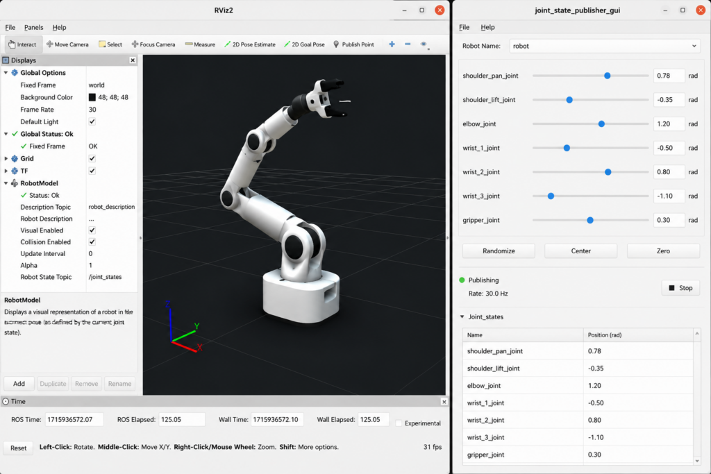
- Verify in RViz2: Launch
rviz2again, and this time, add the [RobotModel] plugin along with the [TF] plugin. Set the Description Source to Topic and select/robot_description, and a wonderful 3D robot will appear right before your eyes. Now, try dragging the sliders in the GUI window with your mouse. You will experience the magic where the slider values are passed torobot_state_publishervia the/joint_statestopic, and the instantly calculated TF transforms are reflected in RViz, making the robot arm move naturally!
Essential Debugging Tools for Researchers: How to Utilize tf2_tools
When dealing with complex robotic systems in graduate research labs or out in the field, you will inevitably encounter error messages like “frames are tangled” or “transform information is missing.” Trying to visually track the fast, real-time stream of the /tf topic in the terminal using the echo command is next to impossible.
In these moments, the fastest and most accurate tool for analyzing the root cause of the problem is the view_frames script from the tf2_tools package.
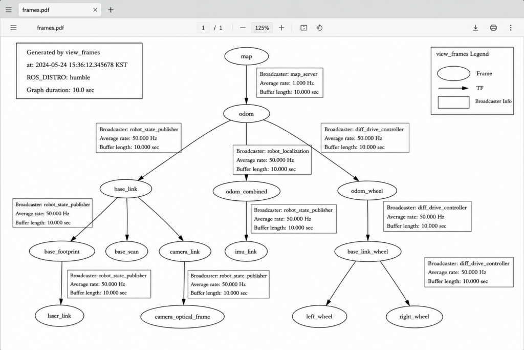
1. Generating the frames.pdf Structure Diagram
With the current robot’s TF frames being broadcasted (with the previous practice session still running), open a new terminal and enter the command below.
ros2 run tf2_tools view_frames
Once the command is executed, the script listens to and analyzes all transform data traveling through the current ROS2 network for about 5 seconds. When the operation is complete, a visualization file named frames.pdf is automatically generated in the directory where you executed the command.
2. Analyzing Debugging Data
Opening the generated PDF file reveals a diagram that allows you to grasp the entire TF tree structure of the current system at a glance. The information within the diagram plays a crucial role in debugging:
- Connection Integrity: You can check at a single glance whether any frames are disconnected, causing the tree to split into two or more separate pieces (i.e., verifying if there is a single root frame).
- Broadcaster: The name of the node broadcasting that specific frame (e.g.,
robot_state_publisherorstatic_transform_publisher) is explicitly stated, allowing you to track down which node is causing an issue. - Average Rate (Hz): For dynamic frames, you can check how many times per second the data is being published. If the update cycle is too slow, it can cause severe latency in control algorithms.
- Time Information (Unix Epoch Time): The long numbers starting with “16314…” displayed on the nodes represent Unix Epoch Time. When using the Gazebo simulator, this displays the time in seconds since the simulator started rather than real-world time, making it highly useful for analyzing time synchronization (Time Sync) issues.
Conclusion
In this [ROS2 Mastery Part 9], we went beyond theory to visually verify the concept of ‘Frame Broadcasting,’ which is the core of the TF2 system.
We took a deep dive into everything from the principles of static transforms (static_transform_publisher) generated with a single line of command, to the brilliant architecture of robot_state_publisher that calculates dynamic joint movements by combining with URDF robot modeling files, and finally to the practical usage of view_frames—a debugging tool that will save researchers precious time.
Up until now, we have utilized the default tools provided by ROS2. However, to develop actual autonomous driving algorithms, we must be able to generate and publish this transform data directly within our own Python code.
In the next [ROS2 Mastery Part 10], building upon the concepts we learned today, we will take a detailed look at how to directly “program a Static Broadcaster” inside a Python node.

Author: Aiden, Marketing Team at QUAD Drone Research Lab
Date: June 5, 2026
![[MAVSDK C++ Part 4] Building Your Own App: Project Setup and Drone Connection](https://quad-drone-lab.co.kr/wp-content/uploads/2026/03/0314_인포그래피-768x512.png)
![[ROS2 Mastery 4편] ROS2 Topic 프로그래밍 (1) – Publisher로 거북이 제어하기](https://quad-drone-lab.co.kr/wp-content/uploads/2026/05/0510_인포그래픽-768x429.png)
![[Hybrid Navigation System Part 4: Integration] Integrating PX4 and External INS Odometry via ROS 2 and Communication Verification](https://quad-drone-lab.co.kr/wp-content/uploads/2026/04/Drone-Navigation-Data-Integration-Flow-1-768x429.jpg)